Magnetic suspension air blower impeller and spindle connecting structure
A blower and magnetic levitation technology, which is applied to the components of the pumping device for elastic fluid, mechanical equipment, non-variable-capacity pumps, etc. State, novel structure design, effect of strong shear force
- Summary
- Abstract
- Description
- Claims
- Application Information
AI Technical Summary
Problems solved by technology
Method used
Image
Examples
Embodiment 1
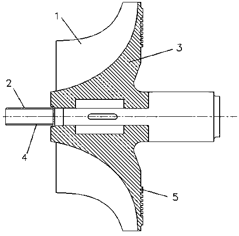
[0024] see figure 1 , the present invention provides a technical solution: a connection form between the impeller and the main shaft of a magnetic levitation blower, including an impeller 1, a motor shaft 2 and a diversion cap 3, the center of the impeller 1 is provided with a shaft hole, and the motor shaft 2 and the The pull rod forms an integrated structure, the motor shaft 2 is connected to the impeller 1 through the shaft hole, and the motor shaft 2 and the impeller 1 are connected through the impeller lock nut 4, the impeller lock nut 4 adopts a circumferential key, and the front end of the impeller 1 A diversion cap 3 is also provided, and a plurality of diversion grooves 5 are evenly distributed on the outer wall of the diversion cap 3 .
[0025] In the present invention, the diversion groove 5 has a U-shaped structure, the width of the diversion groove 5 is 10mm-20mm, and the depth is 5mm-8mm. The diversion groove adopted by the invention can evenly distribute the ai...
Embodiment 2
[0028] Embodiment two:
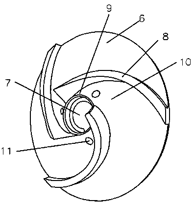
[0029] see Figure 1-2 , a connection form between the impeller and the main shaft of a magnetic levitation blower, including an impeller 1, a motor shaft 2 and a deflector cap 3, the center of the impeller 1 is provided with a shaft hole, and the motor shaft 2 and the tie rod form an integrated structure. The motor shaft 2 is connected to the impeller 1 through the shaft hole, and the motor shaft 2 and the impeller 1 are connected through the impeller lock nut 4, the impeller lock nut 4 adopts a circumferential key, and the front end of the impeller 1 is also provided with a diversion cap 3, A plurality of diversion grooves 5 are evenly distributed on the outer wall of the diversion cap 3 .
[0030] In the present invention, the diversion groove 5 has a U-shaped structure, the width of the diversion groove 5 is 10mm-20mm, and the depth is 5mm-8mm. The diversion groove adopted by the invention can evenly distribute the airflow field, thereby improvin...
PUM
 Abstract
Description
Claims
Application Information
 - R&D
- Intellectual Property
- Life Sciences
- Materials
- Tech Scout
- Unparalleled Data Quality
- Higher Quality Content
- 60% Fewer Hallucinations
Browse by: Latest US Patents, China's latest patents, Technical Efficacy Thesaurus, Application Domain, Technology Topic, Popular Technical Reports.
© 2025 PatSnap. All rights reserved.Legal|Privacy policy|Modern Slavery Act Transparency Statement|Sitemap|About US| Contact US: help@patsnap.com


