A flue gas denitrification mixing device

A mixing device and denitrification technology, which is applied in separation methods, dispersed particle separation, chemical instruments and methods, etc., can solve the problem of low mixing uniformity of flue gas and ammonia gas, so as to improve the reduction efficiency and reduction degree, and improve the mixing uniformity degree, the effect of reducing energy loss

Active Publication Date: 2019-12-03
NINGBO LIANTONG EQUIP MFG
View PDF5 Cites 0 Cited by
  • Summary
  • Abstract
  • Description
  • Claims
  • Application Information

AI Technical Summary

Problems solved by technology

In the flue gas denitrification mixing device at the present stage, only the flue gas and ammonia gas are passed into the mixing chamber together, and then the mixed gas is passed into the denitrification chamber, so that the mixing uniformity of the flue gas and ammonia gas is low, so it is necessary to develop at this stage Developed a flue gas denitrification mixing device with a high degree of uniformity in the mixing of flue gas and ammonia gas

Method used


Image

  • A flue gas denitrification mixing device
  • A flue gas denitrification mixing device
  • A flue gas denitrification mixing device

Examples


Embodiment Construction

[0038] The present invention will be described in further detail below in conjunction with the accompanying drawings.

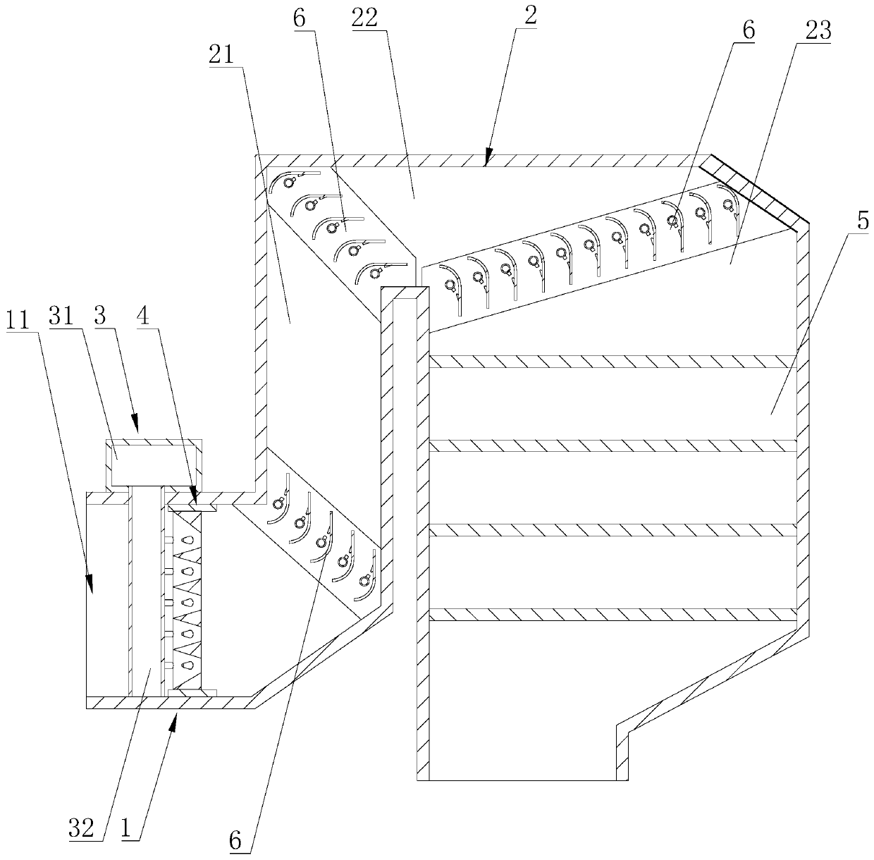
[0039] See attached figure 1 , a flue gas denitration mixing device mainly includes a mixing chamber 1 , a mixing channel 2 , an ammonia injection component 3 and a diversion component 4 . The mixing chamber 1 is in the shape of a cuboid as a whole, and one end of the mixing chamber 1 has a flue gas inlet 11 for the flue gas to pass through, and the other end communicates with the mixing channel 2 . The mixing passage 2 comprises a first passage 21, a second passage 22 and a third passage 23, the first passage 21 is communicated with the tail end top of the mixing chamber 1 and arranged vertically upwards; the second passage 22 is communicated with the tail of the first passage 21 The third channel 23 communicates with the tail end of the second channel 22 and is arranged vertically downward, and the third channel 23 communicates with the top of the denitratio...


PUM


Abstract

The invention discloses a flue gas denitration and mixing device, aiming at solving the problem that flue gas and ammonia gas are not uniformly mixed at the present stage. According to the essentialsof the technical scheme, the flue gas denitration and mixing device comprises a mixing chamber, a mixing channel, an ammonia spraying assembly and a flow guide assembly, wherein the ammonia spraying assembly comprises a plurality of ammonia spraying vertical pipes and an ammonia spraying general pipe; first gaps are formed between the adjacent ammonia spraying vertical pipes; each ammonia sprayingvertical pipe comprises a guide side face and a mounting side face; the ammonia spraying vertical pipes are provided with a plurality of groups of ammonia gas spraying nozzles; the flow guide assembly is located at one side, far away from a flue gas inlet, of the ammonia spraying vertical pipes and comprises flow guide parts which are distributed along the width direction of the mixing chamber atintervals; second gaps, which correspond to the ammonia spraying vertical pipes one by one, are formed between the adjacent flow guide parts; the width of the second gaps is gradually reduced along the direction far away from the flue gas inlet; each flow guide part is provided with a first flow guide plane; the flue gas denitration and mixing device disclosed by the invention can be used for uniformly mixing the flue gas and the ammonia gas, so that the denitration efficiency of nitrogen oxide in the flue gas in a denitration chamber is improved.

Description

technical field [0001] The invention relates to environmental protection equipment, in particular to a flue gas denitrification mixing device. Background technique [0002] Flue gas denitrification is mainly to remove the nitrogen oxides in the flue gas, so as to avoid the pollution of the atmosphere, soil and water due to the high concentration of nitrogen oxides discharged into the atmosphere. The principle of the flue gas denitrification process is that nitrogen oxides are reduced to nitrogen by a reducing agent under the action of a catalyst. The commonly used catalyst is SCR, and the commonly used reducing agent is ammonia. [0003] Due to the principle of the flue gas denitrification process, the flue gas denitrification equipment mainly includes a flue gas denitrification mixing device and a denitrification chamber. The gas reacts, and the nitrogen oxides in the flue gas are reduced to ammonia gas. The uniformity of the mixing of flue gas and ammonia gas directly aff...

Claims


Application Information

Patent Timeline
Patent Type & Authority Patents(China)
IPC IPC(8): B01D53/90B01D53/56
CPCB01D53/8631B01D53/90
Inventor 江远军蔡丽萍王洪军赵春山马韶慧
Owner NINGBO LIANTONG EQUIP MFG
Why Eureka
Try Eureka