
Hydraulic synchronous system and carrying vehicle comprising synchronous hydraulic system

A technology of hydraulic system and hydraulic cylinder, applied in the direction of fluid pressure actuating device, servo motor, servo motor assembly, etc., can solve the problems of poor dynamic characteristics, low control accuracy and low response speed of the pump control system, and achieve high Efficient operation, ensuring stable operation and high efficiency

Inactive Publication Date: 2019-04-12
SHANGHAI SURAY INFORMATION TECH CO LTD
View PDF5 Cites 3 Cited by
  • Summary
  • Abstract
  • Description
  • Claims
  • Application Information

AI Technical Summary

Problems solved by technology

The former uses multiple pumps to input the same flow to each oil cylinder, and controls the output flow of the pump by changing the displacement of the pump, thereby adjusting the movement speed of the actuator. The pump control system has high efficiency and less energy loss, but due to the pump The response speed is not high, the dynamic characteristics of the pump control system are relatively poor, and the control accuracy is not high
[0004] At present, there is no good method to improve the synchronization accuracy at home and abroad. Most of them use the method of correcting the error loop to avoid the accumulated error caused by multiple reciprocating movements, but this is only from the quality of the system components or the structure of the oil circuit. , low stability and low efficiency

Method used


Image

  • Hydraulic synchronous system and carrying vehicle comprising synchronous hydraulic system
  • Hydraulic synchronous system and carrying vehicle comprising synchronous hydraulic system
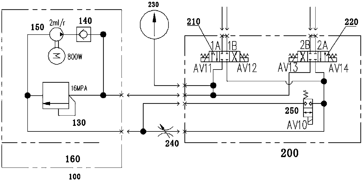
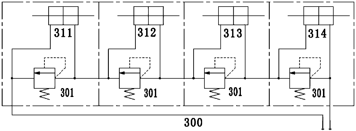
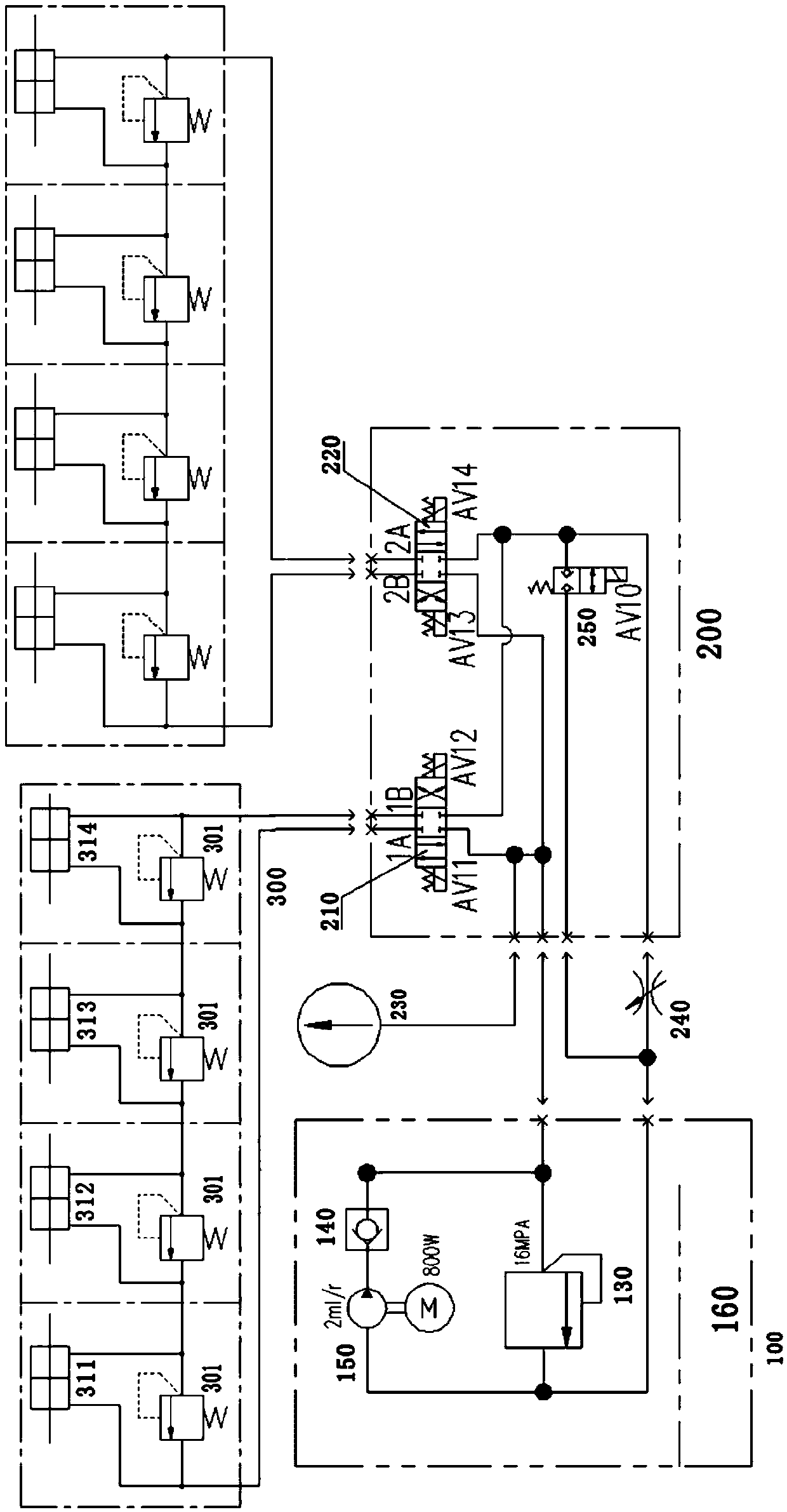
  • Hydraulic synchronous system and carrying vehicle comprising synchronous hydraulic system

Examples


Embodiment Construction

[0022] The objects and functions of the present invention and methods for achieving the objects and functions will be clarified by referring to the exemplary embodiments. However, the present invention is not limited to the exemplary embodiments disclosed below; it can be implemented in various forms. The essence of the description is only to help those skilled in the relevant art comprehensively understand the specific details of the present invention.

[0023] Hereinafter, embodiments of the present invention will be described with reference to the accompanying drawings. In the drawings, the same reference numerals represent the same or similar components, or the same or similar steps.

[0024] According to one aspect of the present disclosure, referring to Figure 1 to Figure 3 As shown, a synchronous hydraulic system is proposed. The synchronous hydraulic system includes a power module 100, a first hydraulic cylinder group 300 driven by the hydraulic oil provided by the ...


PUM


Abstract

The invention discloses a hydraulic synchronous system and a carrying vehicle comprising the synchronous hydraulic system. The invention provides the synchronous hydraulic system. The synchronous hydraulic system comprises a power module, a first hydraulic cylinder set and a reversing valve set, wherein the first hydraulic cylinder set is driven by hydraulic oil provided by the power module, and the reversing valve set is arranged between the power module and the first hydraulic cylinder set. The hydraulic oil of the power module is supplied to the first hydraulic cylinder set through the reversing valve set and then flows back to the backflow end of the power module. The power module comprises an oil tank, a motor and an oil pump driven by the motor. A one-way valve is arranged on an output pipeline of the oil pump. The power module is internally further provided with a first overflow valve for adjusting the pressure of the synchronous hydraulic system. Various hydraulic cylinders inthe first hydraulic cylinder set are connected in series, and each hydraulic cylinder is connected with a second overflow valve in parallel. The invention further discloses the carrying vehicle usingthe synchronous hydraulic system.

Description

technical field [0001] The invention relates to the field of storage equipment, in particular to a synchronous hydraulic system and a carrier including the synchronous hydraulic system. Background technique [0002] In the prior art, there are many realization forms of the hydraulic synchronous system, and its basic forms can be divided into open-loop control mode and closed-loop control mode. The precision of the valve itself controls the synchronization of the actuators. Generally speaking, the hydraulic synchronization system adopting the open-loop control method has a simple structure and low cost, but it cannot eliminate the errors caused by different loads, differences in the manufacturing accuracy of the cylinders, and hydraulic oil leakage. [0003] In addition, the synchronous hydraulic system can also be divided into two types: pump-controlled synchronous control and valve-controlled synchronous control. The former uses multiple pumps to input the same flow to ea...

Claims


Application Information

Patent Timeline
Patent Type & Authority Applications(China)
IPC IPC(8): F15B11/22F15B13/06
CPCF15B11/22F15B13/06
Inventor 许庆波崔磊王龙罗强
Owner SHANGHAI SURAY INFORMATION TECH CO LTD
Learn More