Ceiling lamp with lifting and cable take-up and pay-off functions

A cable and functional technology, applied in the field of lighting tools, can solve problems such as easy rusting of lamps, paint peeling, troublesome maintenance and cleaning of chandeliers, and potential safety hazards

Inactive Publication Date: 2019-04-12
ZHONGSHAN HOUYUAN ELECTRONICS TECH CO LTD
View PDF0 Cites 9 Cited by
  • Summary
  • Abstract
  • Description
  • Claims
  • Application Information

AI Technical Summary

Problems solved by technology

Generally, more beautiful chandeliers usually have more complicated shapes and lampshades. If it is wet and dusty, the lamps are prone to rust and paint, and the lampshade will become increasingly dim due to dust. Thirty, within a few years the chandeliers will be dim and dull
[0004] The existing chandelier is very troublesome to maintain and clean, and it needs to be climbed manually with the help of a ladder, which has potential safety hazards

Method used


Image

  • Ceiling lamp with lifting and cable take-up and pay-off functions
  • Ceiling lamp with lifting and cable take-up and pay-off functions
  • Ceiling lamp with lifting and cable take-up and pay-off functions

Examples


Embodiment 1

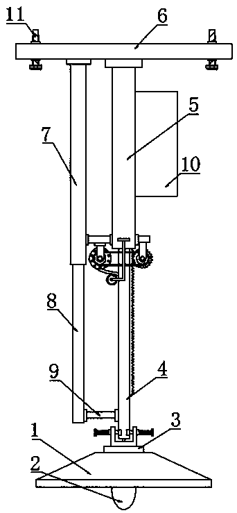
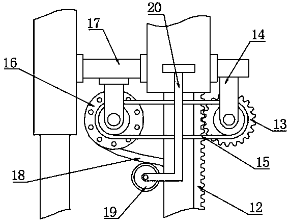
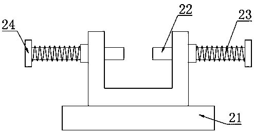
[0025] see Figure 1-4 , a chandelier with lifting and cable retracting functions, including a lampshade 1, a clamping device 3, a telescopic rod 4, a sleeve rod 5 and a take-up roller 16; a light bulb 2 is installed inside the lampshade 1, and the lampshade 1 The upper part is fixedly connected with the clamping device 3, the telescopic rod 4 is arranged above the clamping device 3, the center of the lampshade 1 and the clamping device 3 are provided with a through hole, the left side wall of the telescopic rod 4 is provided with a longitudinal strip-shaped channel, and the telescopic The upper part of the rod 4 fits the sleeve rod 5, and the top of the sleeve rod 5 is fixedly connected to the mounting plate 6, and the lower end of the telescopic rod 4 is fixedly connected to the lampshade 1 through the clamping device 3, so that the lampshade 1 can be easily removed to replace and maintain the bulb 2; The above four corners of the mounting plate 6 are provided with round hol...

Embodiment 2

[0029] see figure 1 , figure 2 and Figure 4 , a chandelier with lifting and cable retracting functions, including a lampshade 1, a clamping device 3, a telescopic rod 4, a sleeve rod 5 and a take-up roller 16; a light bulb 2 is installed inside the lampshade 1, and the lampshade 1 The upper part is fixedly connected with the clamping device 3, the telescopic rod 4 is arranged above the clamping device 3, the center of the lampshade 1 and the clamping device 3 are provided with a through hole, the left side wall of the telescopic rod 4 is provided with a longitudinal strip-shaped channel, and the telescopic The upper part of the rod 4 fits the sleeve rod 5, and the top of the sleeve rod 5 is fixedly connected to the mounting plate 6, and the lower end of the telescopic rod 4 is fixedly connected to the lampshade 1 through the clamping device 3, so that the lampshade 1 can be easily removed to replace and maintain the bulb 2; The above four corners of the mounting plate 6 ar...

Embodiment 3

[0033] see figure 1 , figure 2 and Figure 4 , a chandelier with lifting and cable retracting functions, including a lampshade 1, a clamping device 3, a telescopic rod 4, a sleeve rod 5 and a take-up roller 16; a light bulb 2 is installed inside the lampshade 1, and the lampshade 1 The upper part is fixedly connected with the clamping device 3, the telescopic rod 4 is arranged above the clamping device 3, the center of the lampshade 1 and the clamping device 3 are provided with a through hole, the left side wall of the telescopic rod 4 is provided with a longitudinal strip-shaped channel, and the telescopic The upper part of the rod 4 fits the sleeve rod 5, and the top of the sleeve rod 5 is fixedly connected to the mounting plate 6, and the lower end of the telescopic rod 4 is fixedly connected to the lampshade 1 through the clamping device 3, so that the lampshade 1 can be easily removed to replace and maintain the bulb 2; The above four corners of the mounting plate 6 ar...


PUM


Abstract

The invention discloses a ceiling lamp with lifting and cable take-up and pay-off functions. A clamping device is fixedly connected with the upper part of a lampshade; an expansion rod is arranged above the clamping device; a through hole is formed in the middle of each of the lampshade and the clamping device; a mounting plate is fixedly connected with the top of a loop bar; a circular hole is formed in each of four corners at the upper part of the mounting plate; a fixed bolt penetrates through the circular hole; the fixed bolt is fixedly connected with the top wall of a wall body through threads; a piston rod is arranged on the left side of the expansion rod; an air cylinder is glidingly connected with the upper part of the piston rod in a sealed manner; the mounting plate is fixedly connected with the upper end of the air cylinder; and the lower end of the piston rod is fixedly connected with the lower end of the expansion rod through a synchronizing rod. The ceiling lamp has the advantages that the lower end of the expansion rod is fixedly connected with the lampshade through the clamping device, the lampshade is convenient to dismount to change and maintain a bulb, the pistonrod is driven through pressure change in the air cylinder to expand longitudinally to further drive the synchronizing rod and the expansion rod to synchronically realize a longitudinal adjustment function, and a rotating cable take-up roll rotates to perform cable take-up and pay-off while the expansion rod performs height adjustment.

Description

technical field [0001] The invention relates to a lighting tool, in particular to a chandelier with functions of lifting and retracting cables. Background technique [0002] A chandelier is a high-end decorative lighting that is hung on the indoor ceiling. Whether the chandelier is hung by wires or iron supports, it should not be hung too low, hindering people's normal sight or making people feel dazzling. Take the chandelier in the dining room as an example. The ideal height is to form a pool of light on the dining table without obstructing the sight of everyone on the table. [0003] There are many patterns of chandeliers, commonly used are European-style candlestick chandeliers, Chinese chandeliers, crystal chandeliers, parchment chandeliers, fashion chandeliers, conical cover lanterns, pointed flat cover lanterns, waist cover lanterns, five-pronged ball chandeliers, magnolia cover lanterns, Olive chandeliers and more. Generally, more beautiful chandeliers usually have...

Claims


Application Information

Patent Timeline
Patent Type & Authority Applications(China)
IPC IPC(8): F21S8/06F21V21/36F21V21/22
CPCF21S8/063F21V21/22F21V21/36
Inventor 李群周胡海兵董君峰
Owner ZHONGSHAN HOUYUAN ELECTRONICS TECH CO LTD
Why Eureka
Try Eureka