A method for efficiently detecting dead pixels of small-pitch COB display modules
A display module, small spacing technology, applied in the field of display screen, can solve the problems of high time cost, increased production cost, damage, etc., and achieve the effect of saving time and production cost, reducing the workload of inspection, and having broad application prospects.
- Summary
- Abstract
- Description
- Claims
- Application Information
AI Technical Summary
Problems solved by technology
Method used
Image
Examples
Embodiment 1
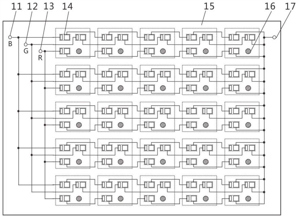
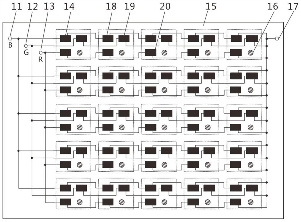
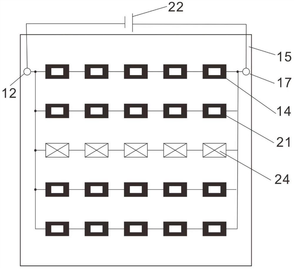
[0050] Taking the P5.0 small-pitch 5cm×5cm COB display module unit as an example, the shape of the small-pitch COB display module substrate 15 is square. For the detection circuit, RGB three chips are preferred to reserve independent row-series-column-parallel circuits. All the figures only draw part of the chips as a schematic representation, and only a single color chip is drawn as a schematic representation in the row detection and dichotomy stages.
[0051] This method comprises the following steps:
[0052] (1) if figure 1 As shown, the small-pitch COB display module substrate 15 reserves a row-series-column-parallel circuit in advance. Row-series means that the electrodes of the color light chip pads 14 in each row are connected in series, that is, the positive pole of each pad is in phase with the negative pole of the previous pad. Connection, the negative pole is connected to the positive pole of the next pad, and the pads on both sides lead out two pins to form a row...
Embodiment 2
[0063] Taking the P5.0 small-pitch 5cm×5cm COB display module unit as an example, the shape of the small-pitch COB display module substrate 15 is square. For the detection circuit, RGB three chips are preferred to reserve independent row-series-column-parallel circuits. All the figures only draw part of the chips as a schematic representation, and only a single color chip is drawn as a schematic representation in the row detection and dichotomy stages.
[0064] The detection steps are generally the same as in Example 1, except that in this embodiment, the whole row of green chip (G) 19 is turned on and tested and found that there are two rows that are not lit, indicating that there are pixels of green chip (G) 19 in both rows Dead pixel chip 23, which belongs to the situation where there are pixel dead pixels in two rows or even multiple rows (n rows), and then the two rows are detected separately, and the two green chips can be found by performing up to 4n dichotomous detectio...
Embodiment 3
[0066] Taking the P5.0 small-pitch 5cm×5cm COB display module unit as an example, the shape of the small-pitch COB display module substrate 15 is square. For the detection circuit, RGB three chips are preferred to reserve independent row-series-column-parallel circuits. All the figures only draw part of the chips as a schematic representation, and only a single color chip is drawn as a schematic representation in the row detection and dichotomy stages.
[0067] The detection steps are generally the same as in Example 1, except that when this embodiment uses the dichotomy method to test the green light chip (G) 19, the two ends are not bright when tested separately, indicating that there are green light chips (G) 19 at both ends. For the dead pixel chips 23, both sides need to perform further dichotomy processing and detection on the undetected chips until all the dead pixel chips 23 of the green light chips (G) 19 are found. This is the case of multiple bad points in a single ...
PUM
 Abstract
Description
Claims
Application Information
 - R&D
- Intellectual Property
- Life Sciences
- Materials
- Tech Scout
- Unparalleled Data Quality
- Higher Quality Content
- 60% Fewer Hallucinations
Browse by: Latest US Patents, China's latest patents, Technical Efficacy Thesaurus, Application Domain, Technology Topic, Popular Technical Reports.
© 2025 PatSnap. All rights reserved.Legal|Privacy policy|Modern Slavery Act Transparency Statement|Sitemap|About US| Contact US: help@patsnap.com


