
Battery pack temperature control device for electric automobile and control method thereof

A temperature control device and electric vehicle technology, applied in the direction of battery circuit devices, circuit devices, secondary batteries, etc., can solve the problem of no integrated heating technology and cooling technology, low output current and output efficiency of batteries, no temperature control system, etc. Problems, achieve convenient and reliable heat exchange, realize energy storage, and realize the effect of heat exchange

Active Publication Date: 2019-04-12
JAPHL POWERTRAIN SYST
View PDF7 Cites 4 Cited by
  • Summary
  • Abstract
  • Description
  • Claims
  • Application Information

AI Technical Summary

Problems solved by technology

For the low-temperature preheating function of the battery pack, the existing solutions generally use PTC to heat the battery pack coolant or use PTC to directly heat the battery cells to achieve this. The disadvantage of this is that it requires both a high-power PTC electric heating device and The control system consumes the electric energy of the battery itself during preheating. The output current and output efficiency of the battery cell are low during preheating, and the preheating speed is slow. In addition, low-temperature charging and discharging of the battery cell itself will cause great damage to the battery cell itself.
In addition, existing battery pack cooling technologies include air-cooled, liquid-cooled, and direct-cooled. The cooling technology is integrated, and the most configured PTC device is also a relatively independent system. There is no overall technology for the temperature control system, and the degree of integration of the control system is not high.

Method used


Image

  • Battery pack temperature control device for electric automobile and control method thereof
  • Battery pack temperature control device for electric automobile and control method thereof

Examples


Embodiment Construction

[0022] Below with reference to the accompanying drawings, through the description of the embodiments, the specific embodiments of the present invention, such as the shape, structure, mutual position and connection relationship between the various parts, the role and working principle of the various parts, etc., will be further described. Detailed instructions:

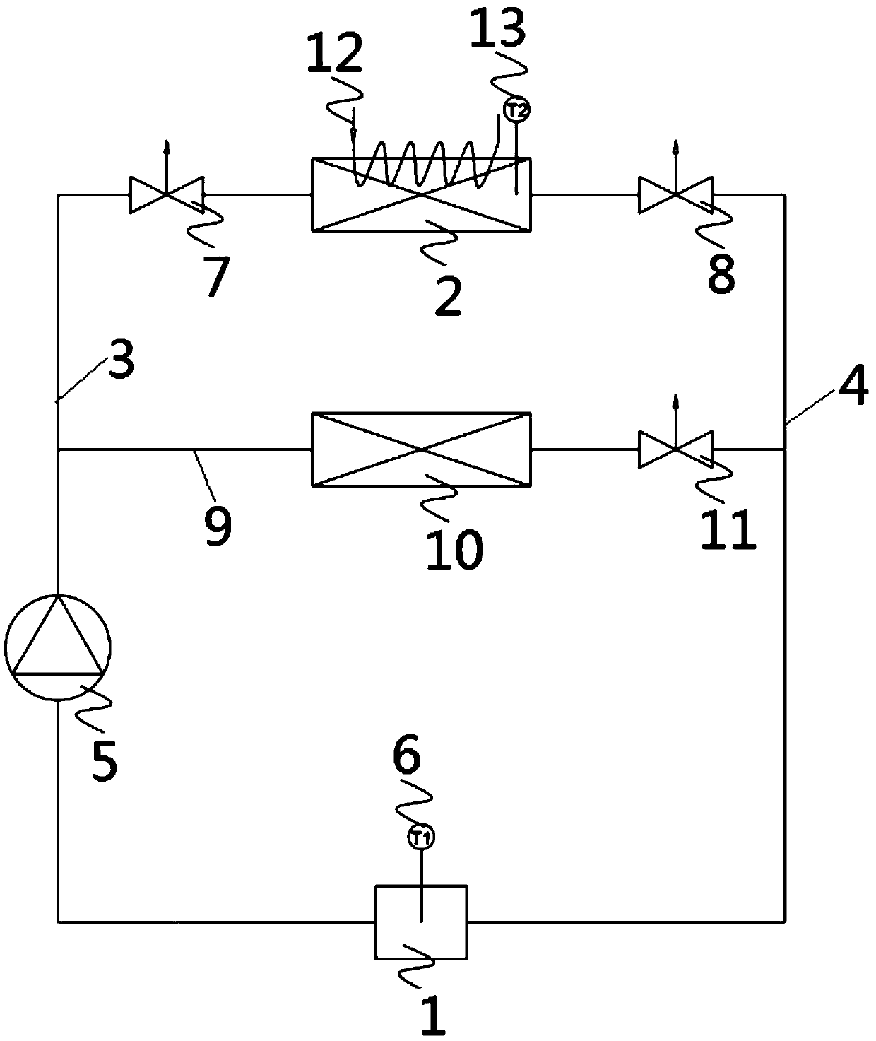
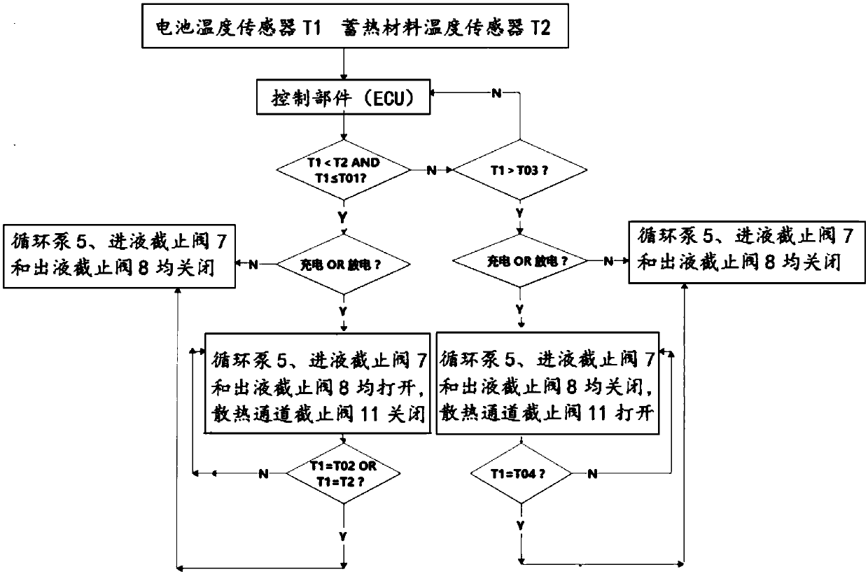
[0023] as attached figure 1 , attached figure 2 As shown, the present invention is a battery pack temperature control device for an electric vehicle. The battery pack temperature control device for an electric vehicle includes a battery pack 1, a heat storage heat exchanger 2, and one end of the heat storage heat exchanger 2 passes through the connecting pipeline I3 It is connected to one end of the temperature control cavity of the battery pack 1, and the other end of the heat storage heat exchanger 2 is connected to the other end of the temperature control cavity of the battery pack 1 through the connecting pipeline ...


PUM


Abstract

The present invention provides a battery pack temperature control device for an electric automobile applied to the technical field of electric automobile parts, and also relates to a control method ofthe battery pack temperature control device for an electric automobile. One end of a regenerative heat exchanger (2) of the battery pack temperature control device for an electric automobile communicates with one end of a battery pack (1) through a connection line I (3); the other end of the regenerative heat exchanger (2) communicates with the other end of the battery pack (1) through a connection line II (4); a connection line III (9) is arranged between the connection line I (3) and the connection line II (4); and the connection line III (9) is provided with a heat dissipation exchanger (10) and a heat dissipation channel globe valve (11). Through the battery pack temperature control device for an electric automobile and the control method of the invention, the battery module in the battery pack can be charged and discharged in the temperature range with high efficiency, the input and output efficiency of the battery module is improved, and the service life and endurance mileage are improved.

Description

technical field [0001] The invention belongs to the technical field of battery pack components for electric vehicles, and more specifically relates to a temperature control device for battery packs of electric vehicles, and also relates to a control method for the temperature control device for battery packs of electric vehicles. Background technique [0002] With the global energy situation becoming more and more tense, and the world's automobile production and sales continue to rise, electric vehicles are becoming more and more popular among governments and people in various countries, and the market share and growth rate of electric vehicles continue to increase. A key technology of electric vehicles lies in the power battery, and the input and output performance, safety and reliability of the power battery are greatly affected by the temperature of the battery cell, so the battery pack thermal management system is particularly important in the design of the electric vehic...

Claims


Application Information

Patent Timeline
Patent Type & Authority Applications(China)
IPC IPC(8): H01M10/42H01M10/48H01M10/613H01M10/615H01M10/633H01M10/635H01M10/6562H01M10/6563H01M10/6568H01M10/657H01M10/659
CPCH01M10/4257H01M10/486H01M10/613H01M10/615H01M10/633H01M10/635H01M10/6562H01M10/6563H01M10/6568H01M10/657H01M10/659H01M2010/4271Y02E60/10
Inventor 杨健春严清梅范礼于芳苏将兵戴国民
Owner JAPHL POWERTRAIN SYST
Learn More