An electrical automatic control cabinet
A technology of electrical automatic control and cabinet body, which is applied to electrical components, substation/switch layout details, substation/distribution device shell, etc. It can solve problems such as difficult to improve work efficiency, time-consuming and labor-intensive, and achieve good heat dissipation effect and reduce dust The effect of entry and easy installation
- Summary
- Abstract
- Description
- Claims
- Application Information
AI Technical Summary
Problems solved by technology
Method used
Image
Examples
Embodiment 1
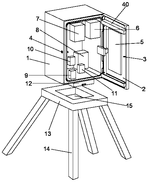
[0028] Embodiment 1: refer to figure 1 ;
[0029] An electric automatic control cabinet, including a cabinet body 1 and a supporting base 13, the front of the cabinet body 1 is hinged to the cabinet door 2, a key lock 4 is provided on one side of the opening of the cabinet body 1, and a lock catch 3 is provided on one side of the cabinet door 2 , the lock catch 3 matches the key lock 4, the front of the cabinet door 2 is provided with a touch screen 5, the back of the cabinet door 2 is provided with a mobile monitoring device 40, and the inside of the cabinet body 1 is fixedly installed with a temperature detector 6 and a humidity detector respectively. 7. Leakage detection protector 8, power protector 9, central processing unit 10 and alarm 11, central processing unit 10 is connected with touch display screen 5, temperature detector 6, humidity detector 7, leakage detection protector 8, The power protector 9 is electrically connected to the alarm 11. The back of the cabinet ...
Embodiment 2
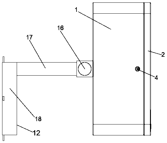
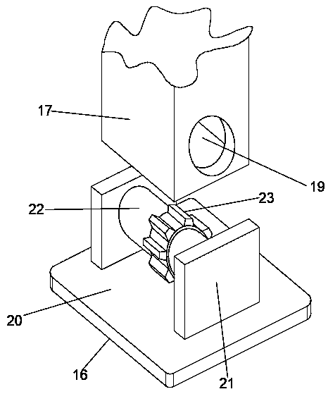
[0032] Embodiment 2: refer to Figure 2-4 , the basis of the embodiment 1 is different in that;
[0033] The supporting and fixing device 12 includes a fixed seat 16, which is fixedly connected to the middle part of the back of the cabinet body 1, the fixed seat 16 is connected to one end of the support rod 17 in rotation, the other end of the support rod 17 is fixed to the upper surface of the deck 18, and the support rod 17 communicates with the card seat 18, and the card seat 18 matches the card slot 15.
[0034] One end of the support rod 17 is provided with a rotating opening 19, and the fixed seat 16 includes a base plate 20, the surface of the base plate 20 is fixedly connected with the middle part of the back of the cabinet body 1, and the left and right sides of the surface of the other side of the base plate 20 are fixedly connected with the splint 21. Fixed shaft 22 is fixedly connected between them, the outer surface of the middle part of the fixed shaft 22 is fix...
Embodiment 3
[0036] Embodiment 3: refer to Figure 5 , the basis of the embodiment 1 is different in that;
[0037] The inner wall of one end of the support rod 17 is fixedly connected with a positioning shaft 26, and the outer surface of the positioning shaft is movably socketed with a rotating gear 24 and a positioning wheel 25 respectively. 23 wheel rims are meshed and connected, and the positioning wheel 25 wheel rims are rotatably connected with the first belt chain 27.
[0038] The bottom of the outer surface around the card holder 18 is provided with a hidden groove 38, which is slidingly connected with the corner seat 39, and the inner end of the corner seat 39 is fixedly connected with one end of the slide fastener 37, and the other end of the slide fastener 37 runs through the bottom of the hidden groove 38 and the The rim of the take-up wheel 35 is fixedly connected, the end surface of the take-up wheel 35 is fixedly connected with the lower end of the support shaft sleeve 34, ...
PUM
 Abstract
Description
Claims
Application Information
 - R&D
- Intellectual Property
- Life Sciences
- Materials
- Tech Scout
- Unparalleled Data Quality
- Higher Quality Content
- 60% Fewer Hallucinations
Browse by: Latest US Patents, China's latest patents, Technical Efficacy Thesaurus, Application Domain, Technology Topic, Popular Technical Reports.
© 2025 PatSnap. All rights reserved.Legal|Privacy policy|Modern Slavery Act Transparency Statement|Sitemap|About US| Contact US: help@patsnap.com


