Check patentability & draft patents in minutes with Patsnap Eureka AI!

Capacitor pre-charging circuit

A technology of pre-charging circuit and power circuit, which is applied in the direction of electrical components, output power conversion devices, etc., can solve the problems of excessive start-up surge current and low reliability, and achieve improved reliability, high power density, improved volume and effect of weight

Pending Publication Date: 2019-04-12
WUHAN YONGLI RAYCO TECH
View PDF10 Cites 1 Cited by
  • Summary
  • Abstract
  • Description
  • Claims
  • Application Information

AI Technical Summary

Problems solved by technology

[0006] The purpose of the present invention is to provide a capacitor pre-charging circuit to solve the problems of excessive power-on surge current and low reliability in the existing pre-charging circuit

Method used


Image

  • Capacitor pre-charging circuit
  • Capacitor pre-charging circuit
  • Capacitor pre-charging circuit

Examples


Embodiment Construction

[0035] The following will clearly and completely describe the technical solutions in the embodiments of the present invention with reference to the accompanying drawings in the embodiments of the present invention. Obviously, the described embodiments are only some, not all, embodiments of the present invention. Based on the embodiments of the present invention, all other embodiments obtained by persons of ordinary skill in the art without making creative efforts belong to the protection scope of the present invention.

[0036] The purpose of the present invention is to provide a capacitor pre-charging circuit, which can improve the reliability of the electronic circuit.

[0037] In order to make the above objects, features and advantages of the present invention more comprehensible, the present invention will be further described in detail below in conjunction with the accompanying drawings and specific embodiments.

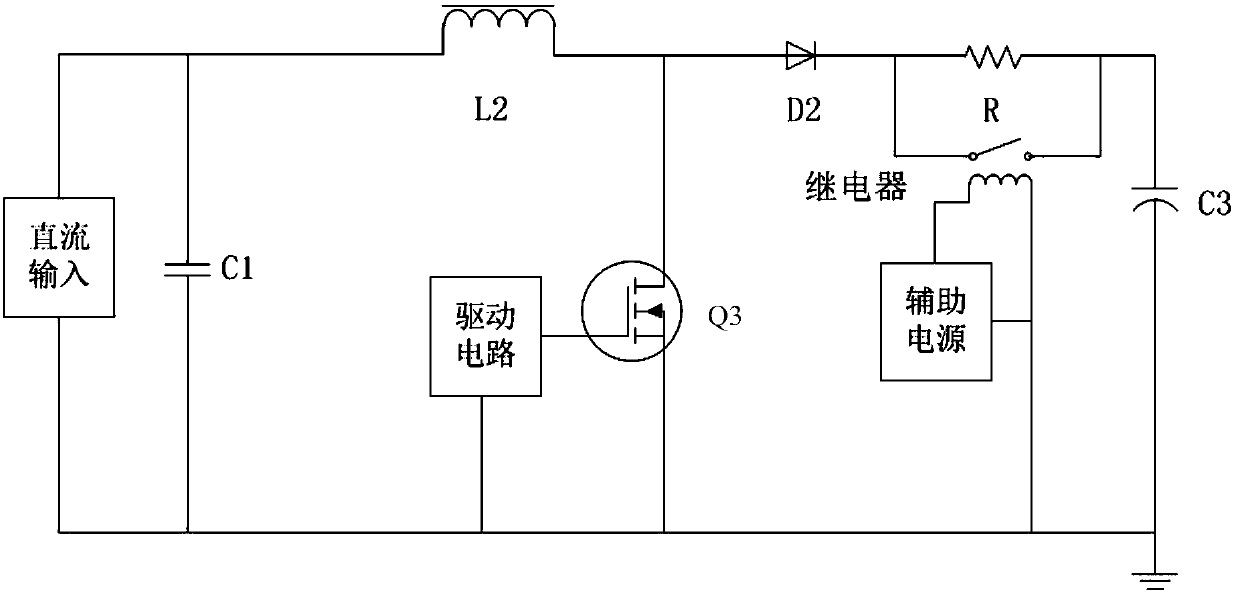
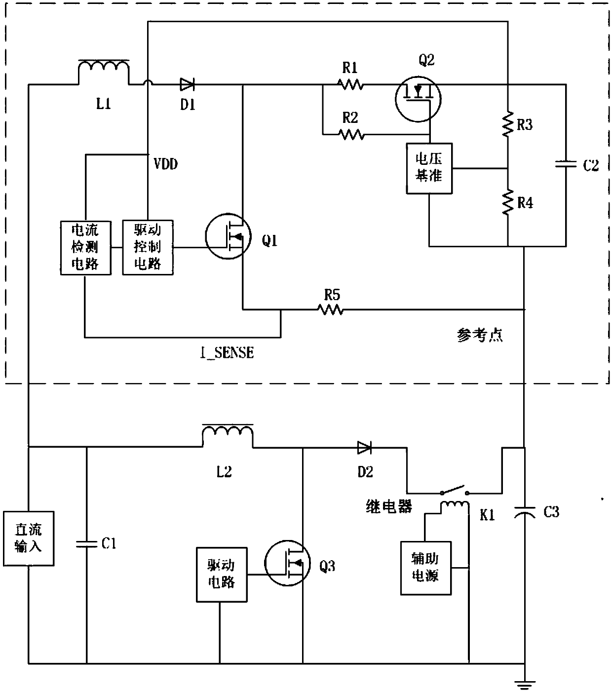
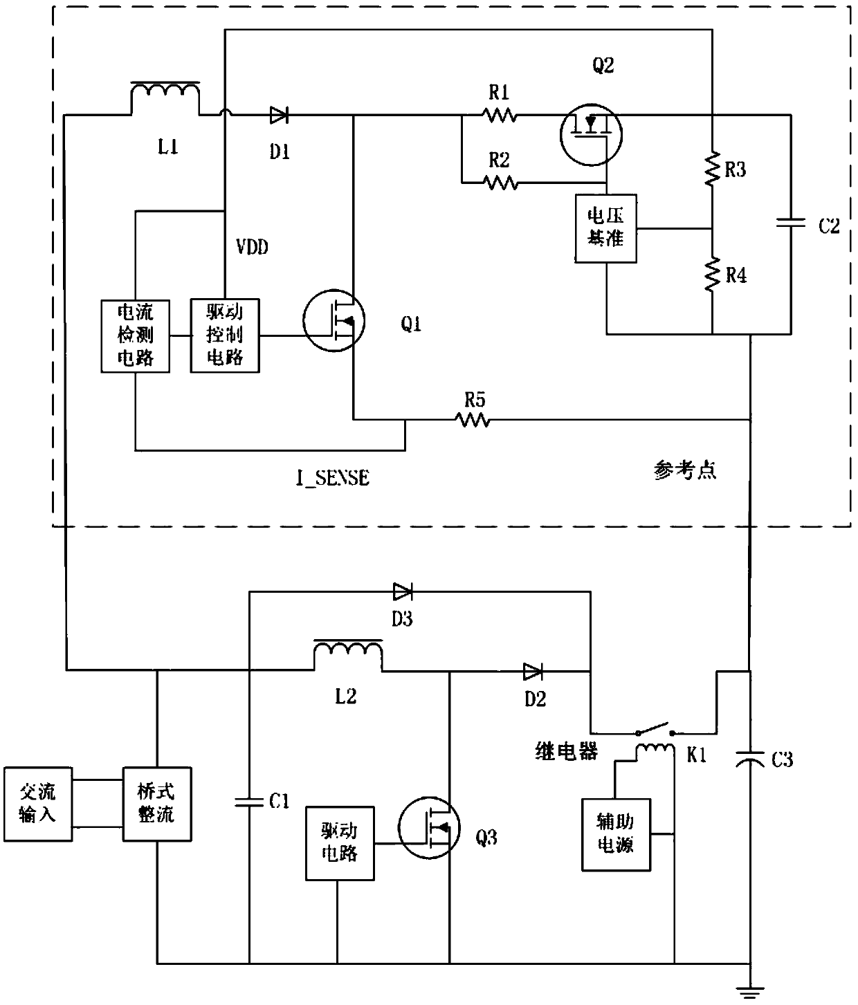
[0038] Such as Figure 2-Figure 4As shown in the inner do...


PUM


Abstract

The invention discloses a capacitor pre-charging circuit. The capacitor pre-charging circuit comprises: an inductor L1, a switch tube Q1, a switch tube Q2, a resistor R1, a resistor R2, a resistor R3,a resistor R4, a resistor R5, a voltage reference, a capacitor C2, a diode D1, a drive control circuit and a current detecting circuit. The capacitor pre-charging circuit disclosed by the invention has the technical effects that the components such as PTC (Positive Temperature Coefficient) resistors, NTC (Negative Temperature Coefficient) resistors or cement resistors and the like in a conventional power supply circuit are replaced, so that the problem that the power is repeatedly turned on and off at very short intervals in a high temperature environment is avoided and the reliability of electronic circuits is increased.

Description

technical field [0001] The invention relates to the field of power electronics, in particular to a capacitor precharging circuit. Background technique [0002] At present, the performance of high-precision equipment on the power supply is getting higher and higher. In order to improve the characteristics of the input and output of the power supply, relatively large capacitors are generally added to the input and output terminals of the power supply. The addition of these input and output capacitors can improve the dynamic characteristics of the power supply. and ripple characteristics. However, the addition of a large capacitor will cause a large inrush current, resulting in an excessive inrush current of the power supply equipment. For example: the capacitor at the input and output terminals of the boost converter (BOOST) boost topology; the capacitor at the output terminal of the boost power factor correction (BOOST-Power Factor Correction, BOOST-PFC) circuit; AC input, a...

Claims


Application Information

Patent Timeline
Patent Type & Authority Applications(China)
IPC IPC(8): H02M1/34
CPCH02M1/34
Inventor 邓卫华孙建涛
Owner WUHAN YONGLI RAYCO TECH
Features
  • R&D
  • Intellectual Property
  • Life Sciences
  • Materials
  • Tech Scout
  • Unparalleled Data Quality
  • Higher Quality Content
  • 60% Fewer Hallucinations
Learn More