A kind of medical intravenous injection auxiliary device
An intravenous injection and auxiliary device technology, applied in the field of medical devices, can solve problems such as aggravating the fear of intravenous infusion
- Summary
- Abstract
- Description
- Claims
- Application Information
AI Technical Summary
Problems solved by technology
Method used
Image
Examples
Embodiment 1
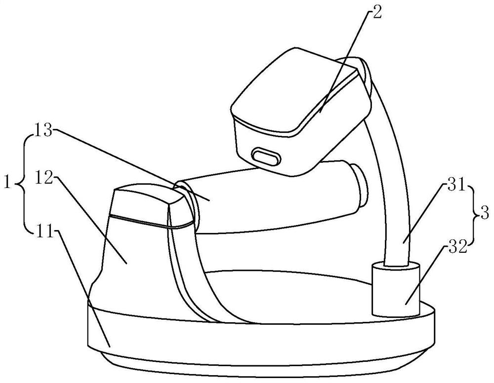
[0032] refer to figure 1, the medical intravenous injection auxiliary device in this embodiment includes a hand support device 1 and a skin stimulation device 2, and the two are connected through a connecting piece 3. Wherein, the hand support device 1 includes a support base 11, a support plate 12 is extended upwards on the support base 11, a hand support rod 13 is horizontally installed on the upper end of the support plate 12, and a non-slip pad is attached to the bottom of the support base 11. - 3 includes a fixed tube 32 and an adjusting tube 31, the fixing tube 32 is installed on the support base 11, one end of the adjusting tube 31 is rotatably connected in the fixing tube 32, the other end of the adjusting tube 31 is connected to the connecting end on one side of the skin stimulating device 2 Plug in, so that the skin stimulating device 2 is fixed on the regulating tube 31 .
[0033] refer to Figure 4 to Figure 7 , the skin stimulation device 2 in this embodiment is...
Embodiment 2
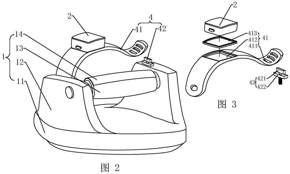
[0041] refer to Figure 2 to Figure 3 , the medical intravenous injection auxiliary device in this embodiment includes a hand support device 1 and a skin stimulation device 2, both of which are connected by a connecting piece 2 4 . Wherein, the hand support device 1 comprises a support base 11, two support plates 12 are arranged symmetrically on the support base 11, a hand support rod 13 is horizontally installed on the upper end of the support plate 12, and a non-slip pad is attached to the bottom of the support base 11, and the connecting piece 2.4 comprises an elastic connecting band 41 and a lock button 42 matched with the connecting band 41, one end of the connecting band 41 is fixed on the support plate 12 on one side of the supporting seat 11, and the other end of the connecting band 41 has a keyhole 412 , the lock button 42 includes two T-shaped lock blocks, wherein the upper lock block 421 and the lower lock block 422 are rotatably connected, and the lower lock block ...
Embodiment 3
[0047] The difference between this embodiment and the first embodiment is that the structure of the skin stimulation device 2 is different, and other structures of this embodiment can refer to the first embodiment.
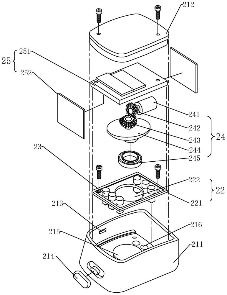
[0048] refer to Figure 9 , the skin stimulation device 2 in this embodiment is in the shape of a cuboid, which includes a main body and a support body 22 located in the main body, a power part three 27, and a plurality of massaging parts 23. specifically:
[0049] The main body includes an opening-shaped containing body 211 and a cover 212 matched with the opening of the containing body 211 to close the containing body 211 , and the massage hole 216 is provided at the lower end of the containing body 211 . The supporting body 22 is a rectangular plate 221 installed in the containing body 211, the center of the supporting body 22 is provided with a limiting groove 222, and the two ends of the supporting body 22 are evenly arranged around the limiting groove 222 f...
PUM
 Abstract
Description
Claims
Application Information
 - R&D
- Intellectual Property
- Life Sciences
- Materials
- Tech Scout
- Unparalleled Data Quality
- Higher Quality Content
- 60% Fewer Hallucinations
Browse by: Latest US Patents, China's latest patents, Technical Efficacy Thesaurus, Application Domain, Technology Topic, Popular Technical Reports.
© 2025 PatSnap. All rights reserved.Legal|Privacy policy|Modern Slavery Act Transparency Statement|Sitemap|About US| Contact US: help@patsnap.com


