

Efficient tail gas treatment device for recycling and processing waste mobile phones
A mobile phone recycling and tail gas treatment technology, applied in transportation and packaging, dispersed particle filtration, dispersed particle separation, etc., can solve the problems of ineffective removal of tail gas impurities and harmful gases, affecting the treatment efficiency of the treatment tank, and low tail gas treatment efficiency, etc. , to prevent clogging, save costs, and increase the probability of contact
- Summary
- Abstract
- Description
- Claims
- Application Information
AI Technical Summary
Problems solved by technology
Method used
Image

Examples
Embodiment 1
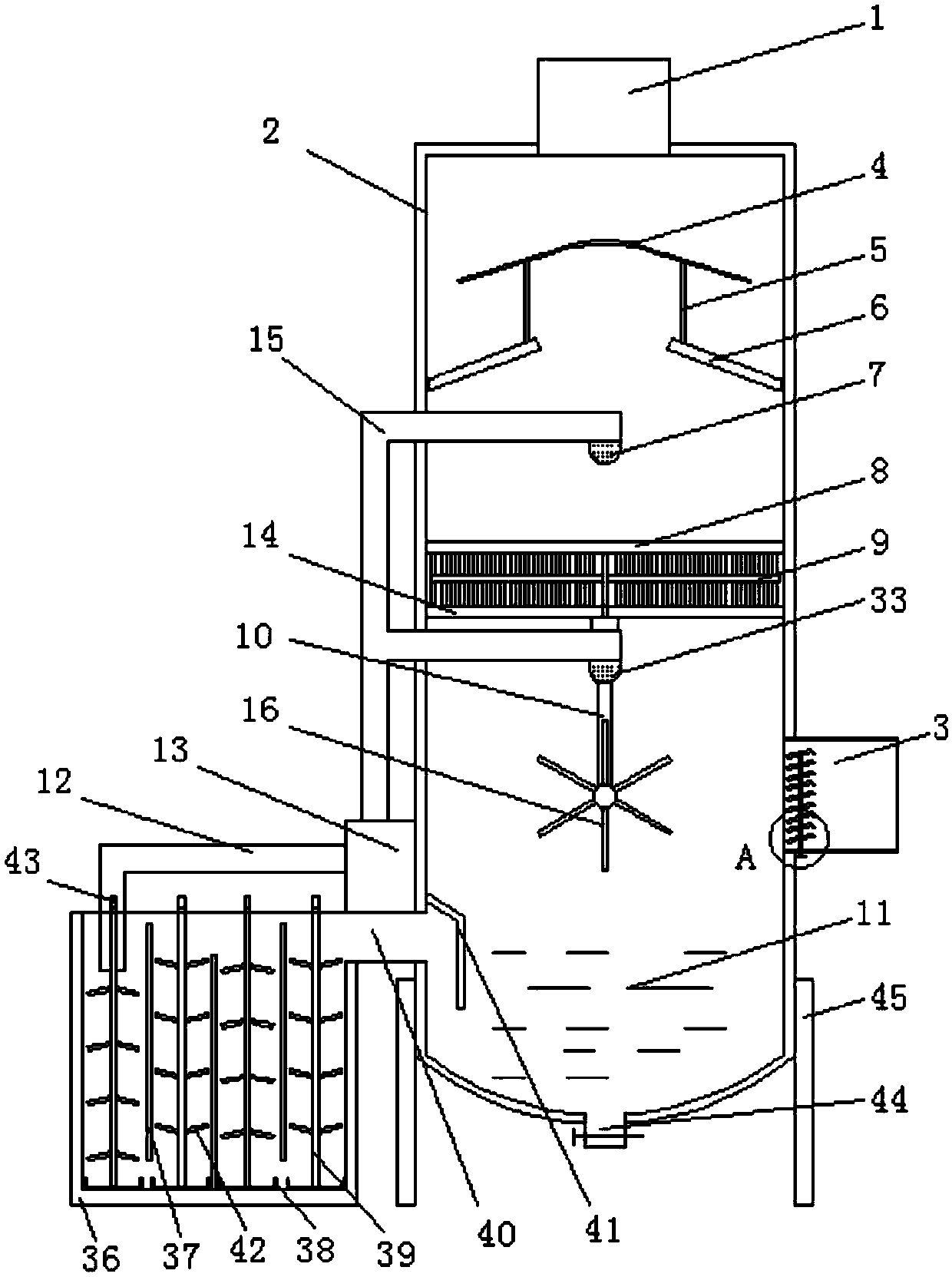
[0031] Example 1, a high-efficiency tail gas treatment device for recycling and processing waste mobile phones, including a treatment tank 2, an air intake pipe 3 and an exhaust pipe 1, the upper end of the treatment tank 2 is provided with an exhaust pipe 1, and the bottom of the treatment tank 2 is a The side is provided with an air intake pipe 3, the middle part of the processing tank 2 is provided with a first nozzle 7, and the inside of the processing tank 2 located at the bottom of the first nozzle 7 is provided with a first dust-proof net plate 8 and a second blocking screen 8 parallel to each other up and down. Dust screen 14, the bottom in the middle of the second dust screen 14 is provided with a second nozzle 33, the processing liquid 11 is provided in the processing tank 2 located at the bottom of the intake pipe 3, and a processing liquid 11 is provided on one side of the processing tank 2. There is a water pump 13, the bottom of the water pump 13 is provided with ...
Embodiment 2
[0036] The same as embodiment 1 is no longer repeated, and the difference with embodiment 1 is:
[0037] Preferably, the middle part of the treatment tank 2 located at the bottom of the exhaust pipe 1 is provided with a flow baffle 4, and the bottom of the flow baffle 4 is provided with a deflector ring plate 6, and the bottom of the deflector ring plate 6 is connected to the treatment tank 2. The inner side wall is fixedly connected, and the first nozzle 7 is arranged at the bottom of the guide ring plate 6 . A baffle and a deflector ring plate are installed at the bottom of the exhaust pipe, which can improve the gas-liquid separation efficiency during gas discharge and reduce the loss of processing liquid.
[0038]Further, the spoiler 4 is hemispherical, the guide ring plate 6 is truncated circular, the diameter of the upper end of the guide ring plate 6 is smaller than the diameter of the bottom, and the diameter of the upper end of the guide ring plate 6 is smaller than t...
Embodiment 3
[0041] The same as embodiment 1 is no longer repeated, and the difference with embodiment 1 is:
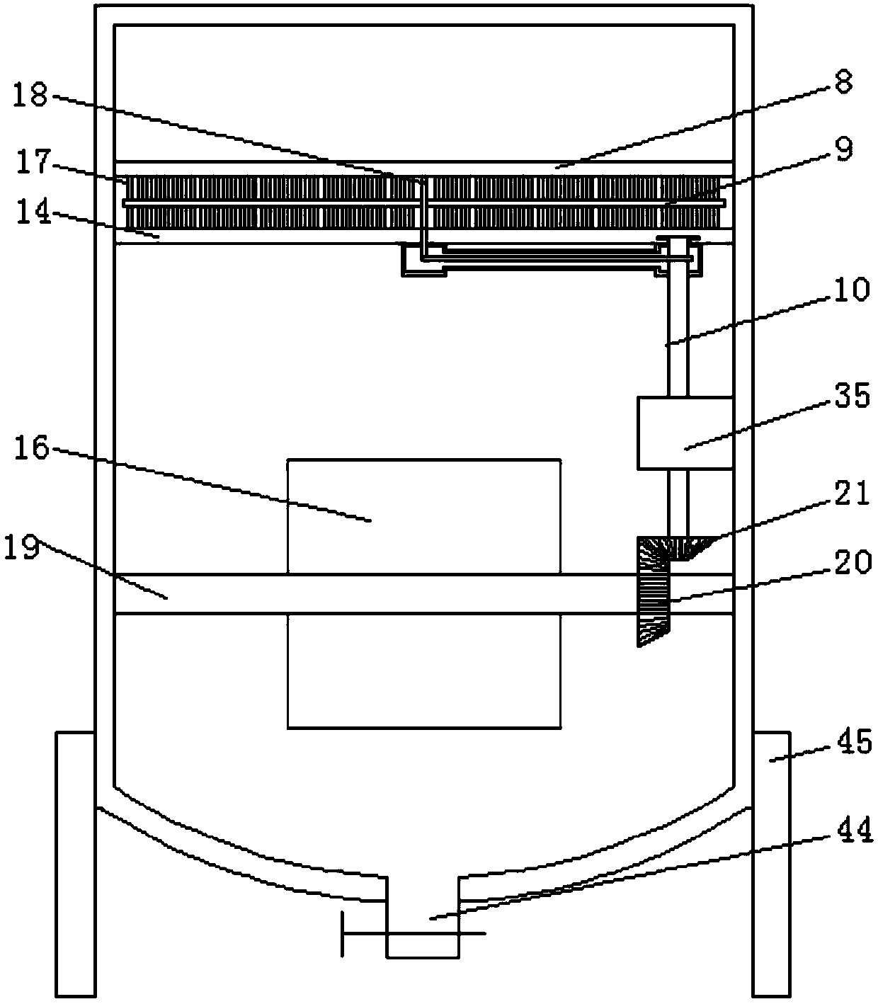
[0042] Preferably, the middle part between the first dust-shielding net plate 8 and the second dust-shielding net plate 14 is provided with a first rotating shaft 18 which is movably connected, and on the first rotating shaft 18 is provided with a number of uniformly axisymmetrically distributed cleaning Rod 9, the upper and lower ends of the cleaning rod 9 are provided with a number of evenly distributed brush filaments 17, and the second rotating shaft 19 that is movably connected is provided in the treatment tank 2 that is flush with the middle of the intake pipe 3. The middle part of the second rotating shaft 19 is provided with a number of evenly distributed baffle plates 16, and one side of the second rotating shaft 19 is provided with a fixedly connected first bevel gear 20, and the bottom of the first rotating shaft 18 passes through the second dust-proof screen 14 , and a...
PUM
 Abstract
Description
Claims
Application Information