
Returning device applied to circulating fluidized bed semi-dry desulfurization

A semi-dry desulfurization and circulating fluidized bed technology, which is applied in the field of fluidized bed desulfurization equipment, can solve the problems of desulfurization ash clogging, high conveying requirements, and difficult material volume control, etc., to achieve improved conveying capacity, simple design structure, and low material consumption. The effect of wide adaptability

Pending Publication Date: 2019-04-16
BEIJING GUODIAN LONGYUAN ENVIRONMENTAL ENG
View PDF0 Cites 1 Cited by
  • Summary
  • Abstract
  • Description
  • Claims
  • Application Information

AI Technical Summary

Problems solved by technology

[0003] In the prior art, the desulfurization ash in the semi-dry desulfurization process of the circulating fluidized bed has the characteristics of small density, small particle size, and easy to be affected by moisture. With a free liquid surface, the fluidity is very strong; after being damp, the desulfurization ash is easy to form agglomerates and agglomerates, and the fluidity is poor
In the first case, the fluidity of desulfurization ash is too strong, and it is difficult to control the amount of material, which may easily cause the phenomenon that the amount of desulfurization ash cannot be controlled; The ash is blocked in the conveying system, and the return system device must adapt to the two working conditions of desulfurization ash, and a large amount of dust is easy to fall on the controller, which is not easy to clean, and will affect the use for a long time, so it is urgently needed to be used in circulating fluidized bed Semi-dry desulfurization return device to solve the above problems

Method used


Image

  • Returning device applied to circulating fluidized bed semi-dry desulfurization
  • Returning device applied to circulating fluidized bed semi-dry desulfurization

Examples


Embodiment Construction

[0017] Before describing the embodiments in detail, it should be understood that the present invention is not limited to the detailed structures or arrangements of elements described herein below or in the accompanying drawings. The present invention can be implemented in other ways. Also, it should be understood that the phraseology and terminology used herein are for descriptive purposes only and should not be interpreted as limiting. The terms "including", "comprising", "having" and similar expressions used herein are meant to include the items listed thereafter, their equivalents and other additional items. In particular, when "a certain element" is described, the present invention does not limit the number of the element to one, but may also include a plurality.

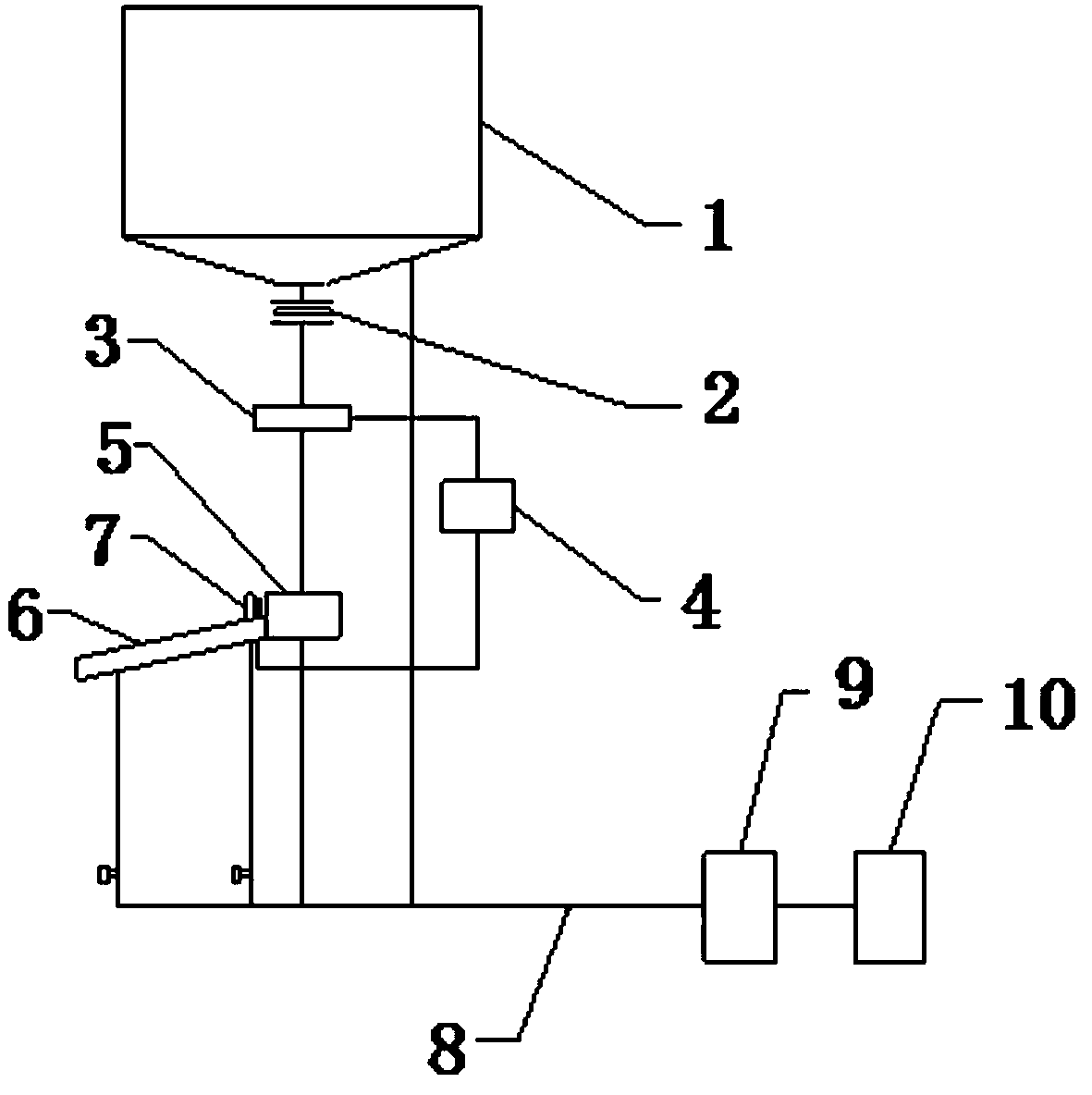
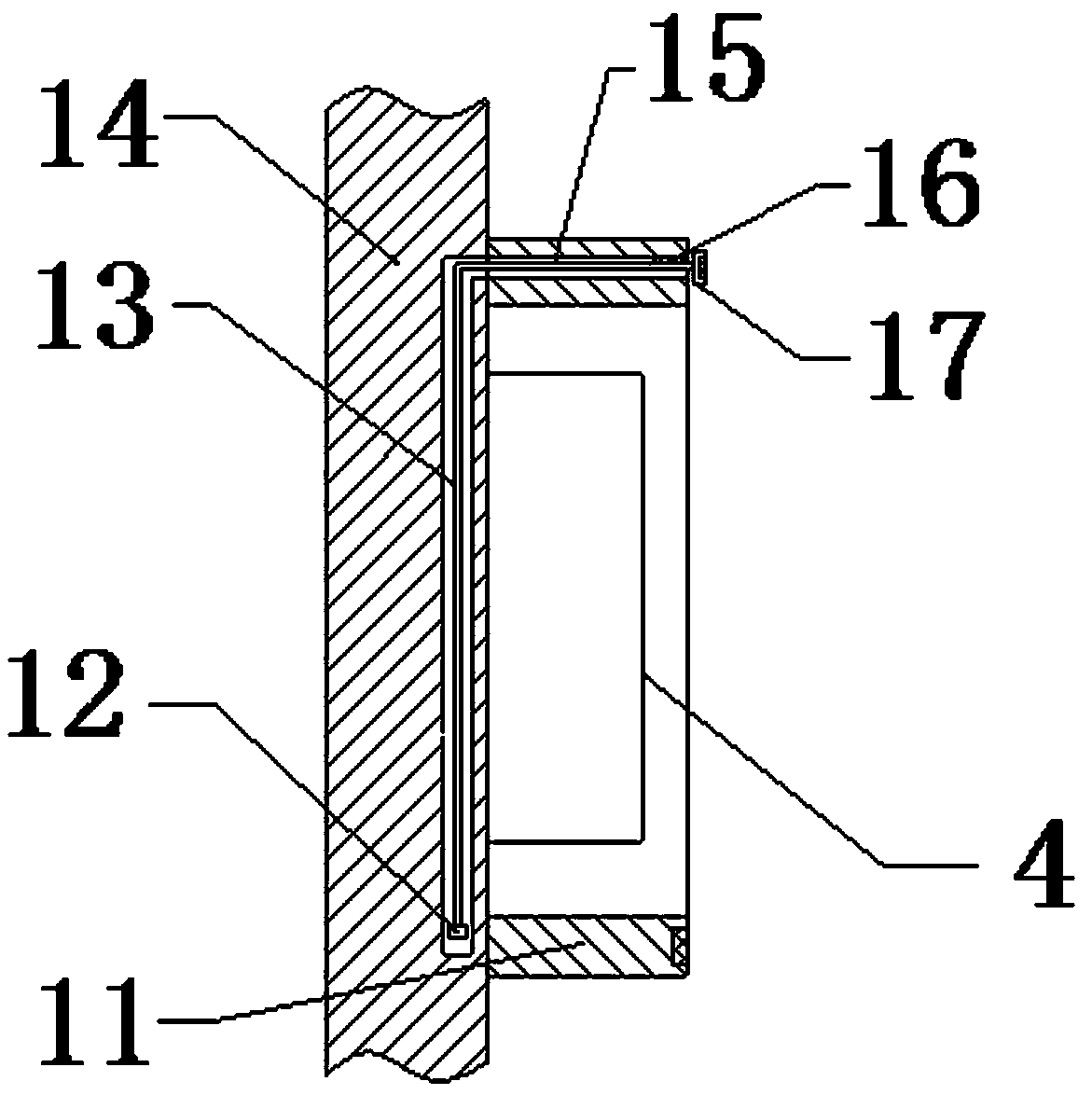
[0018] see figure 1 and figure 2 , the present invention provides a technical solution: the return device applied to semi-dry desulfurization of circulating fluidized bed, including bag filter 1, the lower e...


PUM


Abstract

The invention provides a returning device applied to circulating fluidized bed semi-dry desulfurization. The device comprises a bag dust remover, the lower end of the bag dust remover is connected with a manual plate inserting door, a port of the lower end of the manual plate inserting door is provided with a weighing device, the lower end of the manual plate inserting door is connected to a shipash hopper through a conduit, an air transporting incline groove is fixedly formed in the left end of the ship ash hopper, the right side of the air transporting incline groove is provided with a returning regulating valve, the right side of the ship ash hopper is provided with a returning material controller, and the returning material controller is respectively connected with the weighing deviceand the returning regulating valve through a wire. The device is simple in structure and convenient to operate, the material adaptability is wide, functions of the continuous and stable conveying ofdesulfurization ashes, the precise control of the returning amount, desulfurization ash timely discharging and the like are simultaneously achieved, and for a material with poor mobility, a material conveying capacity is improved by increasing the opening of the regulating valve and increasing a fluidizing wind pressure.

Description

technical field [0001] The invention is a material returning device applied to semi-dry desulfurization of a circulating fluidized bed, and belongs to the field of fluidized bed desulfurization equipment. Background technique [0002] In the circulating fluidized bed semi-dry desulfurization process, the desulfurization ash return system is a key subsystem that affects the desulfurization efficiency and the continuous and stable operation of the entire desulfurization system. At present, the return conveying parts of desulfurized ash in the semi-dry desulfurization process of circulating fluidized bed mainly include three conveying parts: air chute, conveying screw, and scraper machine. The return device is composed of these three conveying parts as the core. Different, more types. [0003] In the prior art, the desulfurization ash in the semi-dry desulfurization process of the circulating fluidized bed has the characteristics of small density, small particle size, and easy...

Claims


Application Information

Patent Timeline
IPC IPC(8): B01D53/80B01D53/48
Inventor 孙丽邢鹏姚宣
Owner BEIJING GUODIAN LONGYUAN ENVIRONMENTAL ENG
Learn More