Radial rotary forging precision forging process and radial rotary forging device for shaft part blind hole

A technology of aperture and shaft type, which is applied in the field of blind hole radial swaging precision forging technology and radial swaging device of shaft parts, which can solve problems such as low efficiency, difficult processing, and reduced material toughness

Active Publication Date: 2019-04-16
山东泰和能源股份有限公司
View PDF8 Cites 17 Cited by
  • Summary
  • Abstract
  • Description
  • Claims
  • Application Information

AI Technical Summary

Problems solved by technology

[0003] For the shape of the missile shell structure, see figure 1 , for the processing of large missile shells, almost all enterprises use traditional processing technology to form large-diameter rod-shaped blanks through free forging technology to form semi-finished forgings with sufficient cutting allowances, and finally cut and process the inner holes according to the drawing size; due to large missiles The inner hole is large, and the traditional cutting method is adopted. On the one hand, it is difficult to process and the cost of cutting loss is high.
In the second aspect, a large amount of material is removed by cutting, resulting in a great waste of material and cost
In the third aspect, the efficiency is low, resulting in a great waste of time
[0004] The invention patent with application publication number CN105057539A discloses a forging die and a forging method for blind hole forgings. From the process link to the forming, it is possible to man

Method used


Image

  • Radial rotary forging precision forging process and radial rotary forging device for shaft part blind hole
  • Radial rotary forging precision forging process and radial rotary forging device for shaft part blind hole
  • Radial rotary forging precision forging process and radial rotary forging device for shaft part blind hole

Examples


Example Embodiment

[0073] In order to deepen the understanding of the present invention, the blind bore diameter direction swiveling precision forging process and radial swaging device of the present invention will be described in further detail with examples and drawings. This embodiment is only used to explain the present invention. It does not constitute a limitation on the protection scope of the present invention.

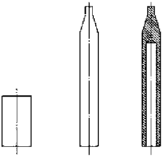
[0074] The new technology of radial forging forming of high-precision large blind hole shell of the present invention can batch manufacture large blind hole shell parts with inner hole diameter of 190mm, length of 1895mm, forging diameter of 310mm, length of 2555mm, and other sizes of blind holes The shell parts can be produced after adjusting the mold, hammer head and process parameters.

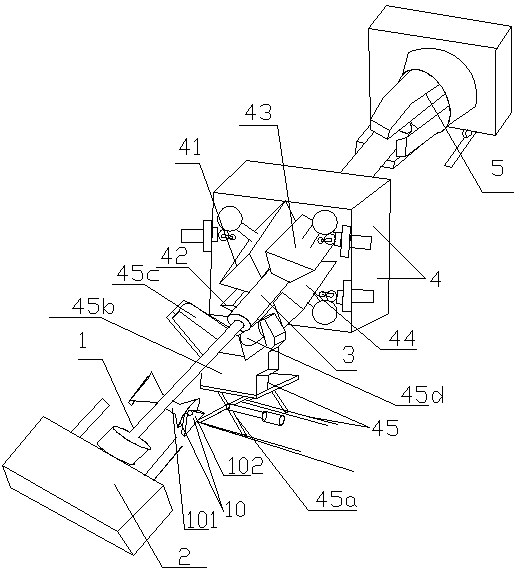
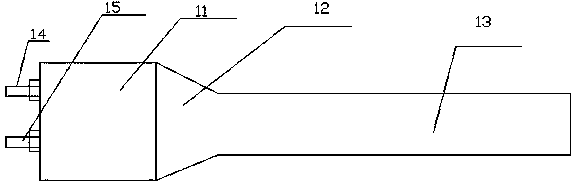
[0075] Such as Figure 1 to Figure 9 As shown, a blind bore diameter direction rotary forging precision forging process and radial rotary forging device for shaft parts, including a core rod 1, a...


PUM


Abstract

The invention provides a radial rotary forging precision forging process and a radial rotary forging device for a shaft part blind hole. The radial rotary forging device includes a core rod, a core rod operating machine, to-be-processed rods, a GFM rotary forging precision forging machine, and a driving clamping head; the GFM rotary forging precision forging machine comprises a left upper hammer head, a left lower hammer head, a right upper hammer head and a right lower hammer head, and the to-be-processed rods are placed between the left upper hammer head, the left lower hammer head, the right upper hammer head and the right lower hammer head; and one end of each to-be-processed rod is clamped on the driving clamping head, the other end of each to-be-processed rod is propped against the core rod, and the end, propped against on the core rod, of each to-be-processed rod is the to-be-processed blind hole end. Compared with a traditional processing technology, the radial rotary forging precision forging process and a radial rotary forging device have the following advantages that (1) materials are saved, processing hours are shortened, the materials are saved, the efficiency is improved, and the manufacturing efficiency is an urgent need for wartime military supply; and (2) the forging performance is high, and compared with an original processing technology, the strength of a shell is greatly improved.

Description

technical field [0001] The invention relates to the technical field of forging processing of shaft parts with blind holes, in particular to a blind hole radial swaging precision forging process and a radial swaging device for shaft parts. Background technique [0002] With the development of modern aviation and military industry, the performance requirements for large-scale missile products are constantly increasing, and large-scale missile shells must also strictly meet quality requirements such as quality, grain size, and sufficient strength to meet the country's needs for military products such as missiles; at the same time , with the rapid development of high-performance fighter jets and large ships, the demand for large missiles is increasing, and the rapid manufacturing and production of missiles has become an important strategic demand in the new era. [0003] For the shape of the missile shell structure, see figure 1 , for the processing of large missile shells, alm...

Claims


Application Information

Patent Timeline
IPC IPC(8): B21J7/16B21J7/04
CPCB21J7/04B21J7/16
Inventor 王涛王永强张岭徐静田广奇
Owner 山东泰和能源股份有限公司
Why Eureka
Try Eureka