
Rapid replacement method for slewing bearing of large continuous casting ladle turret

A technology of slewing bearing and replacement method, applied in casting equipment, casting melt container, metal processing equipment, etc., can solve the problems of construction technology consuming a lot of manpower and material resources, difficult to meet the needs of fast-paced, high-intensity production, and heavy weight.

Active Publication Date: 2019-04-16
SHANGHAI BAOYE GRP CORP
View PDF7 Cites 2 Cited by
  • Summary
  • Abstract
  • Description
  • Claims
  • Application Information

AI Technical Summary

Problems solved by technology

Due to the large size and heavy weight of the slewing bearing and the limitation of equipment and workshops, the existing replacement method is to remove the cross arm of the slewing table first, and then use the equipment to install the hoisting beam, and the molten steel receiving span and the pouring span will cooperate to move the slewing table. Lifting and disengaging the slewing bearing, and then using a 10-ton electric hoist to replace the slewing bearing, the construction process of this replacement operation consumes a lot of manpower and material resources, and is inefficient, making it increasingly difficult to meet the needs of fast-paced, high-intensity production

Method used


Image

  • Rapid replacement method for slewing bearing of large continuous casting ladle turret
  • Rapid replacement method for slewing bearing of large continuous casting ladle turret

Examples


Embodiment Construction

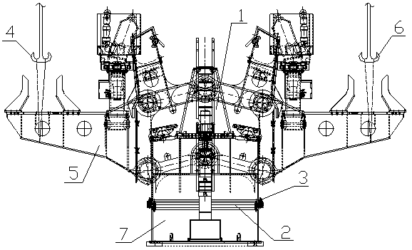
[0022] Example figure 1 and figure 2 As shown, the rapid replacement method of the slewing bearing of the large continuous casting ladle turret of the present invention comprises the following steps:

[0023] Step 1. Fabricate and install the support platform of the turntable on one side of the ladle turntable, and set the support beam of the cross arm of the turntable and the lifting support column for fixing the cross arm of the turntable on the support platform;

[0024] Step 2. Remove the hydraulic slip ring and corresponding oil pipe, electrical slip ring and corresponding electrical circuit in the ladle turret respectively;

[0025] Step 3: Disassemble the connecting bolt 3 between the main body 1 of the ladle turret and the slewing bearing 2, and reserve a connecting bolt at every 90-degree position, and pour the molten steel into the steel straddle crane hook 4 to connect the cross arm 5 of the ladle turret through a steel wire rope. side, the molten steel receiving...


PUM


Abstract

The invention discloses a rapid replacement method for a slewing bearing of a large continuous casting ladle turret. According to the method, a supporting platform, a supporting beam of a turret crossarm and a lifting type supporting column of the turret cross arm are manufactured and installed; connection bolts between a ladle turret body and the slewing bearing are detached, and a molten steelcasting straddle traveling crane hook and a molten steel receiving straddle traveling crane hook are connected with the ladle turret cross arm through steel wire ropes; traveling cranes hoist the ladle turret body away from a base and horizontally move the ladle turret body to the supporting platform; the installation position of the slewing bearing is marked on the base, and the slewing bearing is hoisted and replaced through an electric hoist; the traveling cranes hoist the ladle turret body away from the supporting platform and horizontally move the ladle turret body to the position above the slewing bearing, and the ladle turret body is located on the slewing bearing along arranged guide rods; the connection bolts are installed, and the guide rods are detached; and hydraulic slip rings, electrical slip rings and corresponding parts are installed back, the supporting platform, the supporting beam and the lifting type supporting column are detached, and the replacement operation is completed. By means of the method, the replacement work of the slewing bearing is rapidly completed, the manpower and material resource input is reduced, and the replacement work efficiency is improved.

Description

technical field [0001] The invention relates to a method for quickly replacing the rotary bearing of a large continuous casting ladle rotary table. Background technique [0002] The ladle turret is the most commonly used equipment for carrying and supporting the ladle for pouring in modern continuous casting. The ladle turret is usually set between the columns of the molten steel receiving span and the pouring span. The designed radius of rotation of the ladle makes the nozzle of the ladle at the specified position above the tundish when pouring steel. During molten steel pouring operation, the steel ladle is hoisted on the turntable with the crane on one side of the molten steel receiving span, and the steel ladle is stopped above the tundish to supply its molten steel through the rotation of the turntable. The poured empty ladle is rotated by the turntable, and then transported back to the molten steel receiving span. [0003] The ladle turret is one of the key equipment...

Claims


Application Information

Patent Timeline
IPC IPC(8): B22D41/13
CPCB22D41/13
Inventor 陈涛郑战胜
Owner SHANGHAI BAOYE GRP CORP
Learn More