
Multi-function cutting machine

A cutting machine and multi-functional technology, applied in the field of plate cutting, can solve the problems of height, angle cannot be adjusted, poor applicability, single function, etc., and achieve the effect of increasing cutting function, facilitating clamping, and improving accuracy

Active Publication Date: 2019-04-16
CHINA OTSUKA PHARM CO LTD
View PDF12 Cites 6 Cited by
  • Summary
  • Abstract
  • Description
  • Claims
  • Application Information

AI Technical Summary

Problems solved by technology

[0003] 1. Only the edge of one side of the plate to be cut is positioned and clamped, and the stability is poor, and the clamping fixture of the plate to be cut is prone to rigid damage to the surface of the plate to be cut during the clamping process
[0004] 2. It is suitable for cutting single size and thickness of the plate to be cut, and the practicability is poor
[0005] 3. The cutting function is only suitable for straight line cutting, and the function is relatively simple
[0006] 4. The overall height and angle cannot be adjusted, and the applicability is poor
[0007] 5. The size of the operating table is fixed, and the stability is poor when cutting large-sized plates to be cut

Method used


Image

  • Multi-function cutting machine
  • Multi-function cutting machine
  • Multi-function cutting machine

Examples


Embodiment

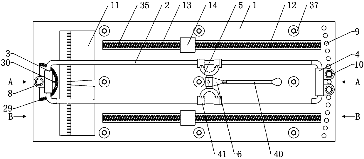
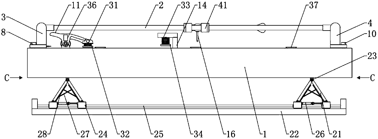
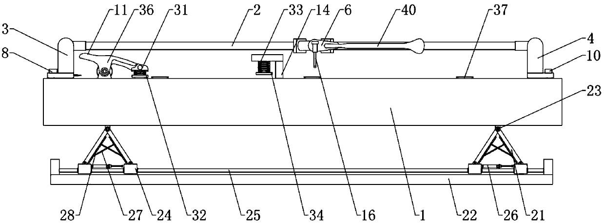
[0042] Embodiment: When the plate to be cut needs to be cut, first, the clamping part 14 is moved to the side of the rectangular groove 12 away from the clamping body 11, and one side edge of the plate to be cut is inserted into the clamping part 14 Open end, and the edge of the other side of the plate to be cut can be clamped and positioned by the clamp body 11, so as to realize the simultaneous positioning of the opposite sides of the plate to be cut, which not only improves the stability of positioning, but also improves the stability during the cutting process. accuracy; when it is necessary to cut the plate to be cut, the bottom of the cutting knife is in contact with the surface of the plate to be cut, and the cutting knife is moved linearly along the guide rod 2 by pulling the pressing handle 40, and finally the plate to be cut is effectively cut by the cutting knife Cutting, wherein the cutting knife has a telescopic function, and the length of the cutting knife can be ...


PUM


Abstract

The invention relates to a multi-function cutting machine. The multi-function cutting machine includes a cutting work table, a cutter assembly used for cutting a plate to be cut, wherein the cutter assembly is slindingly mounted on a guiding rod in a matched mode, the tail end of a cutter fixing column is hinged to a cutter with extensible function, a first connecting block is rotatably connectedwith the upper end surface of the cutting work table through a pin shaft, a second connecting block is locked in the screw holes of the cutting work table through locking bolts, one side of the upperend surface of the cutting work table is fixedly connected with a clamped clamping body used for clamping the edge of one side of the plate to be cut, at least two rectangular grooves are formed in the upper end surface of the cutting work table, clamping parts for clamping the edge of the other side of the plate to be cut are arranged on a sliding rod in a sliding mode, and an adjusting part foradjusting the height and the inclination angle of the cutting work table is arranged at the lower end of the cutting work table. According to the multi-function cutting machine, stability of positioning, accuracy of cutting and the application range of using are improved, the operation is convenient for workers, and the multi-function cutting machine is applicable to cutting plates with a certainthickness range and a certain size range.

Description

technical field [0001] The invention belongs to the technical field of plate cutting, and in particular relates to a multifunctional cutting machine. Background technique [0002] Sheet metal cutting machine is a commonly used tool in the field of sheet metal cutting. According to the power source, it is divided into electric sheet metal cutting machine and manual sheet metal cutting machine. Although the electric plate cutting machine has high cutting efficiency, it is heavy, noisy, and dusty, which is very harmful to the health of the operator. The manual plate cutting machine is small in size, noiseless, dust-free, and is not affected by the power supply. Therefore, it is widely used in indoor operation. Chinese patent CN207757883U discloses "a portable high-efficiency ceramic tile cutting machine", which includes a cutting workbench, a first support column is symmetrically installed on one end of the top of the cutting workbench, and a second support column is symmetric...

Claims


Application Information

Patent Timeline
IPC IPC(8): B28D1/22B28D7/00B28D7/04B26D3/10B26D7/02B26D7/26
CPCB26D3/10B26D7/025B26D7/2628B28D1/22B28D7/00B28D7/04
Inventor 于玥
Owner CHINA OTSUKA PHARM CO LTD
Learn More