Clothing printing device

A printing and clothing technology, applied in printing, printing presses, transfer printing, etc., can solve the problems of reduced fit, cumbersomeness, and reduced clothing fixing ability, and achieve the effect of convenient repair and replacement

Inactive Publication Date: 2019-04-16
颍上县艺豪服饰辅料有限公司
View PDF12 Cites 3 Cited by
  • Summary
  • Abstract
  • Description
  • Claims
  • Application Information

AI Technical Summary

Problems solved by technology

[0003] There are certain disadvantages in the existing garment printing device. (1) When the inside of the device is damaged and needs to be repaired, it is necessary to use tools to disassemble the outer shell of the device, and then repair the inside of the device. This process is too cumbersome and affects Timely use of the garment printing device; (2) When the garment printing device is printing, it is necessary to use the clamping frame to fix the position of the outer surface of the garment printing to prevent the garment from sliding during printing. After long-term use or when the size is different, the clamping frame and the The degree of fit between the printing stations is reduced, and the ability to fix the garment is reduced; (3), when the garment is printed, if there are wrinkles on the surface of the garment, it is necessary to use an iron to level the surface of the garment before printing, which increases the work Steps, prolong working hours, affect the progress of the work, for this reason, we propose a garment printing device

Method used


Image

  • Clothing printing device
  • Clothing printing device
  • Clothing printing device

Examples


Embodiment 1

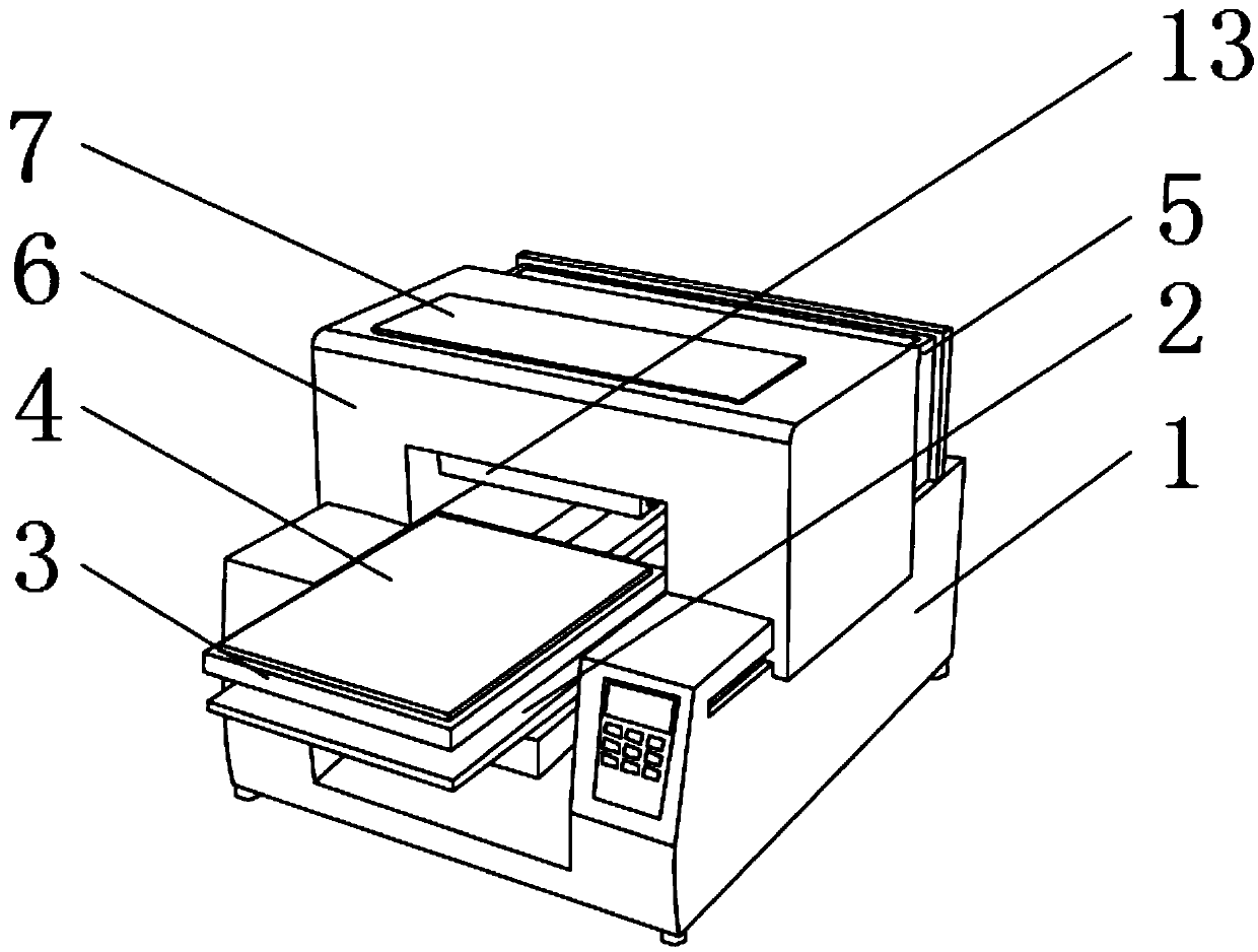
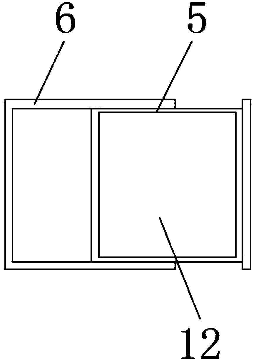
[0032] refer to figure 2 As shown, the position of the top outer surface of the base 1 close to the fixed frame 5 is movably installed with a sliding shell 6 through the slide rail, and the top outer surface of the sliding shell 6 is movably mounted with a feeding plate 7 through a hinge, and the inside of the fixed frame 5 is opened. There are circuit slots 12 .

[0033] refer to figure 2 The outer surface of the rear end of the fixed frame 5 is inlaid with a lock cylinder near the top position, and the fixed frame 5 and the sliding shell 6 are conveniently fixed by installing the lock core, and the outer surface of the rear end of the sliding shell 6 is welded near the position of the fixed frame 5 The handle is provided on the surface of the sliding housing 6 to facilitate maintenance personnel to slide the sliding housing 6 forward.

[0034] By installing slide rails on both sides of the sliding housing 6, the sliding housing 6 can be easily slid forward and backward. ...

Embodiment 2

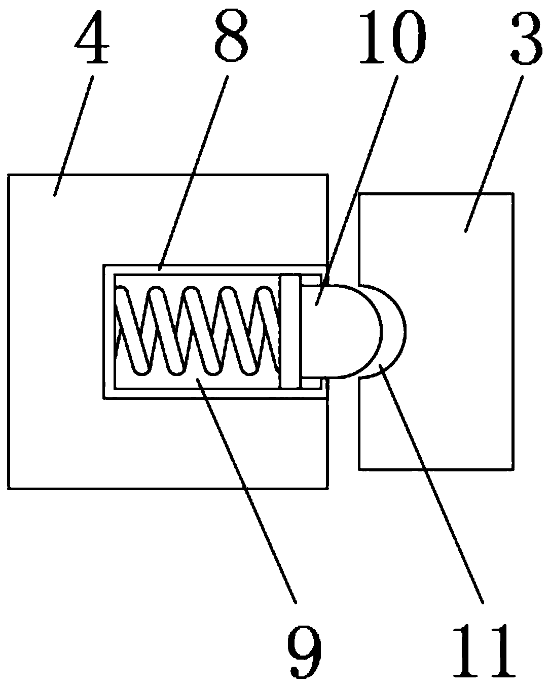
[0036] refer to image 3 As shown, the inside of the printing table 4 is fixedly installed with a shrinking frame 8 close to the position of the clamping frame 3, and the inside of the shrinking frame 8 is provided with a shrinking groove 9, and the inner surface of the shrinking groove 9 is equipped with an extrusion head 10 through a spring. A groove 11 is formed on the inner surface of the frame 3 near the extrusion head 10 .

[0037] By setting the extruding head 10 that can expand and contract on the outer surface of the printing table 4, when the clothing is fixed, the extruding head 10 will squeeze the clothing between the printing table 4 and the clamping frame 3 under the action of the rear end spring. Pressing, fixed by extrusion, can closely fit clothes of different thicknesses, and at the same time, a groove 11 is opened at the position close to the extrusion head 10 inside the clamping frame 3, when the extrusion head 10 stretches When the clothes are squeezed in...

Embodiment 3

[0039] refer to Figure 4-6 As shown, the outer surface of the bottom end of the sliding housing 6 is fixed with an ironing frame 13 by bolts near the front end, and the outer surface of the bottom end of the ironing frame 13 is provided with a placement groove 14, and the inner bottom surface of the placement groove 14 is close to the positions on both sides. Laser range finder 15 is fixedly installed, and the outer surface of the bottom end of ironing frame 13 is provided with a plurality of atomizing nozzles 17 near the front position, and the inside of ironing frame 13 is fixedly equipped with electric telescopic rod 18 near both sides. And between the two groups of electric telescopic rods 18, a shaft rod 20 is welded, and the outer surface of the shaft rod 20 is movably installed with a hot pressing roller 16 through a bearing, and a heating wire 19 is arranged between the hot pressing roller 16 and the shaft rod 20 .

[0040] refer to Figure 4 , one side outer surface...


PUM


Abstract

The invention discloses a clothing printing device. The clothing printing device comprises a base, wherein a guide table is movably installed at the middle position, near the front end position, of the outer surface of the top end of the base, a printing table is fixedly installed on the outer surface of the top end of the guide table through bolts, a clamping frame is movably installed on the outer surface of the printing table, and a fixing frame is welded to the position, near the end, of the outer surface of the top end of the base. According to the clothing printing device, firstly, various parts installed in the fixing frame can be observed more intuitively, so that the parts can be repaired and replaced conveniently; secondly, clothes with different thicknesses can be tightly attached, and when an extrusion head is extended, the clothes can be matched with a groove, so that the clothes can be fixed better; finally, an atomizing nozzle sprays water on the surface of the clothes for humidifying, and then a hot pressing roller flattens the surfaces of the clothes, so that subsequent printing is convenient; and meanwhile, a bleeding point absorbs and removes dust on the surfaceof the clothes, so that a better use prospect is brought.

Description

technical field [0001] The invention relates to the field of clothing printing, in particular to a clothing printing device. Background technique [0002] The printing machine is suitable for printing on various materials. After refitting, the application range of the printing machine is wider, no longer limited to paper printing. The printing machine is mainly divided into thermal transfer printing machine, digital printing machine, flat screen printing machine and rotary screen printing machine, Walking printing machine, etc.; [0003] There are certain disadvantages in the existing garment printing device. (1) When the inside of the device is damaged and needs to be repaired, it is necessary to use tools to disassemble the outer shell of the device, and then repair the inside of the device. This process is too cumbersome and affects Timely use of the garment printing device; (2) When the garment printing device is printing, it is necessary to use the clamping frame to fi...

Claims


Application Information

Patent Timeline
Patent Type & Authority Applications(China)
IPC IPC(8): B41F16/02B41F22/00B41F33/00
CPCB41F16/02B41F22/00B41F33/00
Inventor 易友志
Owner 颍上县艺豪服饰辅料有限公司
Why Eureka
Try Eureka