Waste resource recycling device for urban landscape gardens

A technology of waste resources and scenery, applied in the field of waste resource recycling, can solve the problems of inability to guarantee the complete crushing of waste, affecting extrusion molding, high labor intensity, etc., and achieve the effect of improving recycling effect, stable movement, and convenient composting and fermentation.

Pending Publication Date: 2022-07-15
SHANGHAI INSTITUTE OF TECHNOLOGY
View PDF1 Cites 0 Cited by
  • Summary
  • Abstract
  • Description
  • Claims
  • Application Information

AI Technical Summary

Problems solved by technology

[0005] The purpose of the present invention is to provide a recycling device for waste resources used in urban landscape gardens, which solves the problem that the waste materials cannot be completely crushed in the crushing process, which wil

Method used


Image

  • Waste resource recycling device for urban landscape gardens
  • Waste resource recycling device for urban landscape gardens
  • Waste resource recycling device for urban landscape gardens

Examples


Embodiment 1

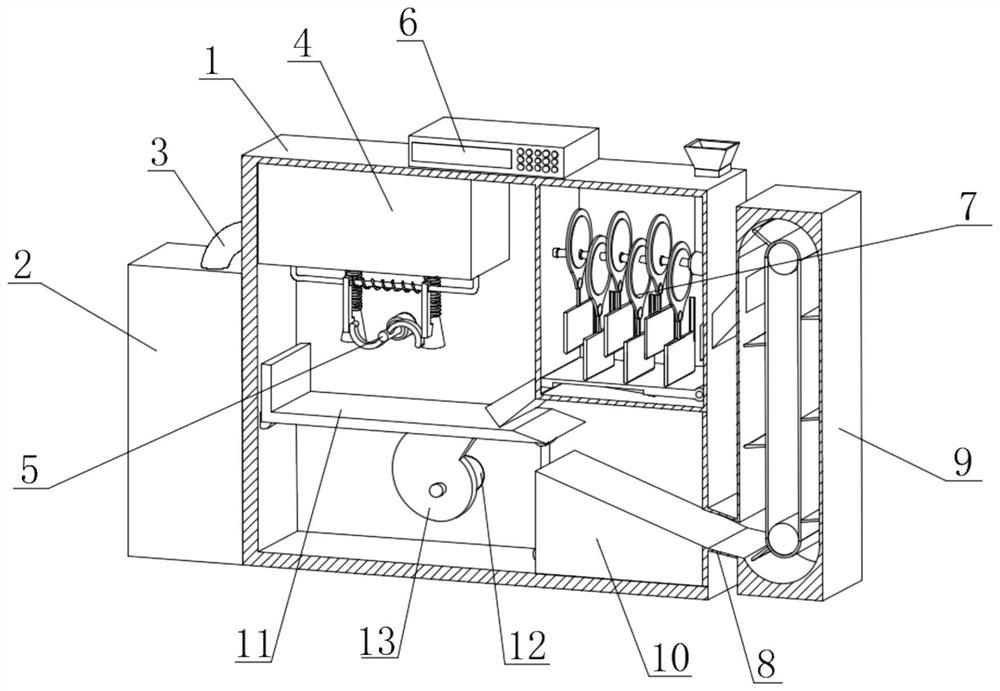
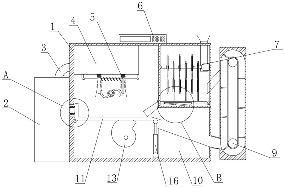
[0033] see Figure 1-Figure 6, the present invention provides a technical solution: a waste resource recycling device for urban landscape gardens, comprising a device body 1, a fan body 4 is fixedly connected to the top inner wall of the device body 1, and a mobile fan body 4 is fixedly connected to the bottom of the fan body 4 Device 5, a PLC controller 6 is fixedly connected to the top center of the device body 1, a crushing device 7 is fixedly connected to the top inner wall of the device body 1, and a circulation pipe 8 is fixedly connected to the outer wall of the device body 1 away from the stacking device 2. , one side of the circulation pipe 8 is fixedly connected with the circulation conveying device 9, the bottom inner wall of the device body 1 is fixedly connected with the material guide table 10, and one side of the material guide table 10 is communicated with one side of the circulation pipe 8. The large particles such as wood that are unloaded from the feeding ta...

Embodiment 2

[0038] see Figure 1-Figure 2 and Figure 7 As shown, on the basis of the first embodiment, the present invention provides a technical solution: the moving device 5 includes a limit slide bar 501, the top of the limit slide bar 501 is fixedly connected with the bottom of the fan body 4, wherein the limit slide bar 501 is fixedly connected The rod 501 is fixedly connected with the fan body 4, which is convenient for stable placement. The outer wall of the limit slide rod 501 is sleeved with a telescopic spring 502, and the outer wall of the limit slide rod 501 is located at both ends of the telescopic spring 502. A fan head 504 is fixedly connected to the bottom of the block 503, and a fan pipe 505 is fixedly connected to the top of the fan head 504. The fan pipe 505 is an elastic pipe. 504 moves synchronously, which is convenient to drive the fan tube 505 to stretch back and forth, and at the same time does not prevent the fan body 4 from sucking the scraps. The inner wall of...

Embodiment 3

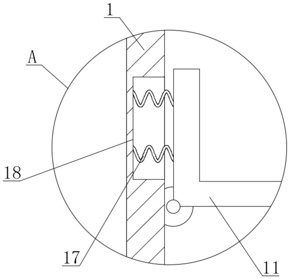
[0041] see Figure 8-Figure 9 As shown, on the basis of Embodiment 1 and Embodiment 2, the present invention provides a technical solution: a stacking device 2 is fixedly connected to one side outer wall of the device body 1, and a connecting pipe 3 is fixedly connected to the top of the stacking device 2 , a screening motor 12 is fixedly connected to the inner wall of one side of the device body 1 and located below the L-shaped plate 11, a cam 13 is connected to one side of the screening motor 12 in rotation, and a bottom groove 14 is opened at the bottom of the L-shaped plate 11. The cam The top of the cam 13 is in contact with the inner wall of the bottom groove 14, and the cam 13 will continuously contact the bottom groove 14 when it rotates. Since the position of the cam 13 and the motor shaft of the screening motor 12 does not change, the L-shaped plate 11 will gradually tilt. The side of the L-shaped plate 11 close to the inner wall of the device body 1 is fixedly conne...


PUM


Abstract

The invention discloses a waste resource recycling device for urban landscape gardens, and relates to the technical field of waste resource recycling, the waste resource recycling device comprises a device body, the inner wall of the top of the device body is fixedly connected with a fan body, and the bottom of the fan body is fixedly connected with a moving device; a PLC is fixedly connected to the center of the top of the device body. Collected dead leaves and residual branches in a landscape garden are added through a feeding hopper, after being treated by a material crushing device, crushed materials are discharged through a discharging pipe and fall on an L-shaped plate, the L-shaped plate is inclined and then discharged through a material guide table, then the crushed materials enter a circulating material conveying device through a circulating pipe, and waste materials entering a circulating box fall on a material conveying plate and are conveyed to a material conveying pipe through a conveying belt; the waste enters the material crushing box again through the material conveying pipe, so that repeated cyclic material crushing is facilitated, the primarily crushed waste can be crushed more thoroughly, subsequent composting fermentation is more convenient, the cyclic utilization effect of the landscape garden waste is effectively improved, and the treatment efficiency is improved.

Description

technical field [0001] The invention relates to the technical field of waste resource recycling, in particular to a waste resource recycling device used in urban landscape gardens. Background technique [0002] The rational utilization of the organic waste produced by landscape gardens has a huge effect. In order to replace the manual operation, the collection of fallen leaves and the like before subsequent treatment, the existing technology has set up the waste resource recycling of urban landscape gardens. Use the device. [0003] For example, Chinese patent CN113953002A discloses a waste resource recycling device for urban landscape gardens. It is equipped with a crushing device and is equipped with a stirring device, so as to ensure sufficient crushing and stirring after the raw materials are added, so that the raw materials are in the form of broken particles. It can be discharged in the shape of the raw material, so as to carry out the subsequent extrusion molding, wh...

Claims


Application Information

Patent Timeline
IPC IPC(8): B09B3/35B02C18/00B02C18/02B02C18/04B02C18/22B02C23/12
CPCB09B3/00B02C18/0084B02C18/02B02C18/04B02C18/2216B02C23/12
Inventor 魏烨双
Owner SHANGHAI INSTITUTE OF TECHNOLOGY
Why Eureka
Try Eureka