Ice surface sliding tool

A tool and ice surface technology, applied in the field of ice sliding tools, can solve the problems of poor power output and durability, and difficult to promote in a large area.

Active Publication Date: 2019-04-16
杨松梅
View PDF8 Cites 0 Cited by
  • Summary
  • Abstract
  • Description
  • Claims
  • Application Information

AI Technical Summary

Problems solved by technology

In view of this, the present invention provides a simple structure, reasonable design, can be realized, to

Method used


Image

  • Ice surface sliding tool
  • Ice surface sliding tool
  • Ice surface sliding tool

Examples


specific Embodiment approach 1

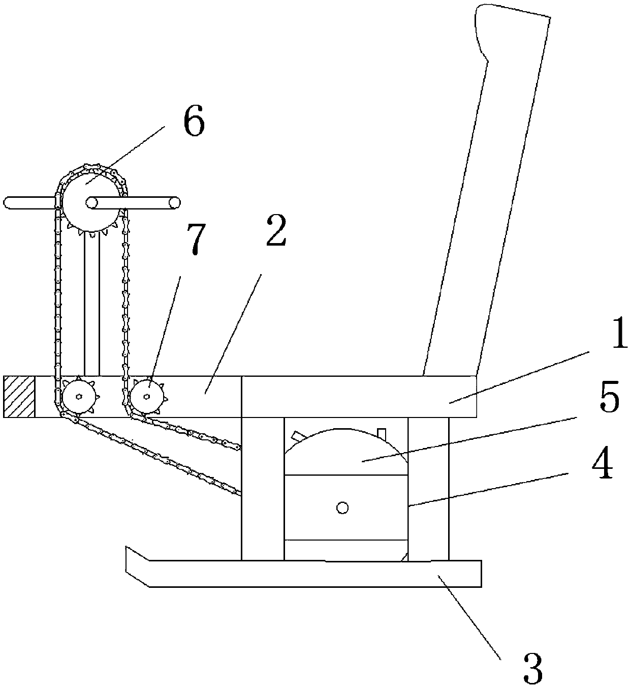
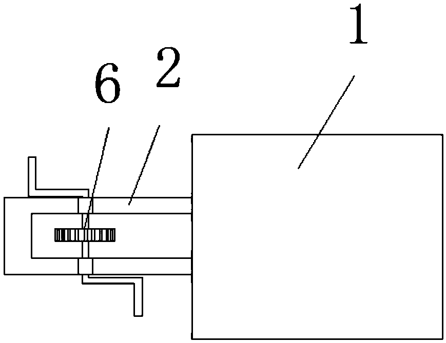
[0051] Such as figure 1 , 2 , 3 and 5, a kind of ice gliding tool disclosed in this embodiment includes a seat plate 1, a U-shaped bar 2, a slide plate 3, an H-shaped connecting frame 4, a pushing device 5, a hand crank 6 and a variable To the gear 7; one end of the upper end surface of the seat plate 1 is provided with a backrest, the other end side wall of the seat plate 1 is provided with a U-shaped rod 2, and the lower end of the seat plate 1 is provided with two slide plates 3 in parallel and symmetrically, The slide plate 3 is connected to the lower end surface of the seat plate 1 through an H-shaped connecting frame 4, and a pushing device 5 is arranged to rotate between the two H-shaped connecting frames 4, and the manual tooth plate 6 is arranged on the U-shaped bar 2 through a strut. At the upper end, the manual crankset 6 is connected with the pusher 5 through a chain, and the chain passes through the U-shaped bar 2 and cooperates with the reversing gear 7, and the...

specific Embodiment approach 2

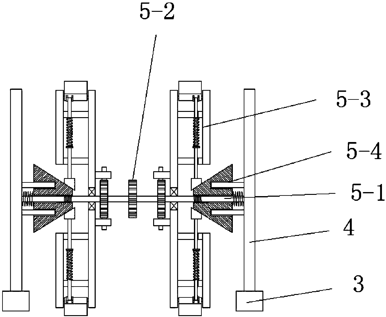
[0058] combine image 3 , 4 , 5, 6, 7 and 8, this embodiment is based on the specific embodiment one, the difference is that the rotating device 5-3 includes a disc 5-3-1, a ratchet 5-3-2, Limiting piece 5-3-3, cylinder 5-3-4, connecting plate 5-3-5, annular disc 5-3-6, transmission rod 5-3-7, trapezoidal limiting block 5-3-8 , the first pressure spring 5-3-9 and the friction member 5-3-10; the disc 5-3-1 is set on the rotating shaft 5-1 through the bearing, and the ratchet 5-3-2 is set on the disc 5-3-1 Between the 3-1 and the rotating shaft 5-2, two limiters 5-3-3 are arranged symmetrically on the center of the inner wall of the disc 5-3-1, and the limiter 5-3-3 and the ratchet 5-3- 2, the outer wall of the disc 5-3-1 is connected with the annular disc 5-3-6 through the cylinder 5-3-4, a plurality of connecting plates 5-3-5 and the rod shaft, and the plurality of connecting plates 5-3-6 - The 3-5 ring array is on the outer wall of the disc 5-3-1, the connecting plate 5-3-...

specific Embodiment approach 3

[0061] combine image 3 , 5 As shown in and 9, this embodiment is based on the first embodiment, the difference is that the positioning device 5-4 includes a conical platform 5-4-1, a limit rod 5-4-4 and a return spring 5-4-5; the center of the conical table 5-4-1 is provided with a through cavity 5-4-2, the through cavity 5-4-2 is provided with internal threads, and the two ends of the through cavity 5-4-2 are symmetrically opened Limit cavity 5-4-3, one end of the limit rod 5-4-4 arranged in parallel and symmetrically is arranged on the H-shaped connecting frame 4, and the other end is set in the limit cavity 5-4-3, and the conical platform 5 -The outer side wall of -4-1 links to each other with the H-shaped connecting frame 4 through the return spring 5-4-5 on the rotating shaft 5-1, the inclined side wall of the conical platform 5-4-1 and the trapezoidal limit block 5-3- 8 against each other;

[0062] When the internal thread in the through cavity 5-4-2 of the conical p...


PUM


Abstract

The invention discloses an ice surface sliding tool, and belongs to the technical field of sliding tools. The problems that power output and durability are poor and large-area popularization is not easy are solved. The ice surface sliding tool comprises a seat plate, a U-type rod piece, slide plates, H-type connecting frames, a pushing device, a hand-cranking chain wheel and a turning gear. A backrest is arranged at one end of the upper end face of the seat plate. The U-type rod piece is arranged on the side wall of the other end of the seat plate. The two slide plates are symmetrically arranged at the lower end of the seat plate in parallel. The slide plates are connected with the lower end face of the seat plate through the H-type connecting frames. The pushing device is rotationally arranged between the two H-type connecting frames. The hand-cranking chain wheel is arranged at the upper end of the U-type rod piece through a supporting rod. The problems that power output and durability are poor and large-area popularization is not easy are solved, and the effects of realizing the continuous and effective power output and meanwhile reducing the resistance of the sliding tool in the sliding stage, thereby making the sliding tool long in sliding distance, high in durability and easy to popularize are achieved.

Description

technical field [0001] The invention belongs to the technical field of skating tools, in particular to an ice skating tool. Background technique [0002] In winter in the north, there is a world of ice and snow everywhere. Ice and snow are a unique wealth for northerners. Northerners love ice and snow, and have created a unique ice and snow culture by looking at ice and snow resources from a cultural perspective. It is possible to make full use of ice and snow and vigorously develop ice and snow tourism culture. How to make tourists better enjoy the enjoyment brought by the world of ice and snow is a key issue. Ice gliding tools can allow tourists to quickly enjoy the fun of ice gliding. Feel the charm of ice and snow. Existing gliding tools, such as ice sledges, need to be pierced on the ice with a sharp iron rod at one end to push the ice sledge to slide forward. It requires certain skills and is dangerous, and the power is poor. The distance is short and the experience ...

Claims


Application Information

Patent Timeline
IPC IPC(8): B62B13/00B62B17/00
CPCB62B13/00B62B17/00
Inventor 宋文利李智鹏张萍杨蕊竹宁博文于阳洋张宇新韩冰
Owner 杨松梅
Why Eureka
Try Eureka