Multifunctional photovoltaic outer shutter

A photovoltaic louver, multi-functional technology, applied in the direction of photovoltaic modules, photovoltaic power generation, windows/doors, etc., can solve the problem of reducing the power generation efficiency and heat insulation performance of photovoltaic venetian blinds, the high application cost of photovoltaic louver external windows, and the easy accumulation of dust in photovoltaic louver Problems such as power generation efficiency, to achieve the effect of improving power generation and heat insulation performance, lowering temperature, and improving shielding

Active Publication Date: 2019-04-16
JIANGSU SDL ENERGY CONSERVATION TECH CO LTD
View PDF4 Cites 5 Cited by
  • Summary
  • Abstract
  • Description
  • Claims
  • Application Information

AI Technical Summary

Problems solved by technology

However, there are still some shortcomings in the existing photovoltaic venetian blinds. For example, the maximum inclination of the photovoltaic venetian blinds is about 70°, and the shading performance is poor, which effectively reduces the power generation efficiency and heat insulation performance of the photovoltaic venetian blinds; It is greatly affected by temperature and is generally installed on the outside of the outer window, but the photovoltaic louver is exposed to the outside for a long time and is prone to dust accumulation, which greatly reduces its power generation efficiency
[0003] In addition, the existing photovoltaic louvers and the ventilation and haze removal of the external windows are rarely combined, and they are often used independently, resulting in a high overall application cost of the photovoltaic louvers. Corresponding technologies for haze integration

Method used


Image

  • Multifunctional photovoltaic outer shutter
  • Multifunctional photovoltaic outer shutter
  • Multifunctional photovoltaic outer shutter

Examples


Embodiment Construction

[0027] The present invention will be further elaborated below through specific embodiments in conjunction with the accompanying drawings.

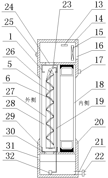
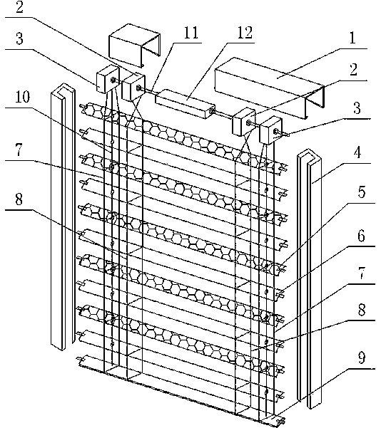
[0028] see Figure 1 to Figure 7 , the present embodiment provides a multi-functional photovoltaic louver exterior window, comprising a triple-glazed window, an upper ventilation structure 14 and a lower ventilation structure 20, the triple-glazed window comprising an outer glass 26, a first cavity 28, a double-layer The insulating glass 18 and the photovoltaic louver system 27 arranged in the first cavity 28 .

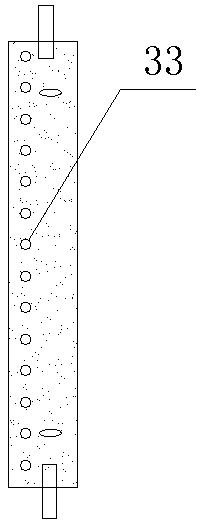
[0029] The photovoltaic louver system 27 includes a top slot 1 fixed on the bottom of the upper ventilation structure 14, a driving device 12 arranged in the top slot 1, a transmission shaft 11, a bottom beam 9, and a plurality of water holes 33 on the left part of the plurality of pieces. The first photovoltaic louver 5, the second photovoltaic louver 6 with a plurality of water holes 33 on the right part, the lifting rope 10 fo...


PUM


Abstract

The invention discloses a multifunctional photovoltaic outer shutter. The shutter comprises a three-layer glass window, an upper ventilation structure and a lower ventilation structure, the three-layer glass window comprises a first cavity and a photovoltaic shutter system, and the photovoltaic shutter system comprises multiple first photovoltaic shutters, multiple second photovoltaic shutters, alifting rope, a first stair rope, a second stair rope, a first rope rolling device and a second rope rolling device; the first photovoltaic shutters and the second photovoltaic shutters are alternatively distributed at equal intervals, the upper end of the first stair rope is fixed to the first rope rolling device in the first preset winding direction, and the upper end of the second stair rope isfixed to the second rope rolling device in the second preset winding direction; the multifunctional photovoltaic outer shutter further comprises a water distributor, a water pump, a first water pipeand a water collection groove. The multifunctional photovoltaic outer shutter is simple in structure, the shielding performance and power generation efficiency of the photovoltaic shutter system can be effectively improved, the application electricity of an air conditioner indoors in summer is effectively reduced, and the indoor air humidity is increased.

Description

technical field [0001] The invention relates to the field of photovoltaic and energy-saving exterior windows, in particular to a multifunctional photovoltaic shutter exterior window. Background technique [0002] Photovoltaic venetian blinds are a product that installs solar cells on the surface of the louvers to generate electricity. It has dual functions of sunshade and photovoltaic power generation. It has been applied in more and more construction projects. However, there are still some shortcomings in the existing photovoltaic venetian blinds. For example, the maximum inclination of the photovoltaic venetian blinds is about 70°, and the shading performance is poor, which effectively reduces the power generation efficiency and heat insulation performance of the photovoltaic venetian blinds; It is greatly affected by temperature and is generally installed on the outside of the outer window. However, the photovoltaic louver is exposed to the outdoors for a long time and is...

Claims


Application Information

Patent Timeline
Patent Type & Authority Applications(China)
IPC IPC(8): E06B9/264E06B9/32E06B9/322E06B9/326E06B9/386H02S40/42F24F6/00
CPCE06B9/264E06B9/32E06B9/322E06B9/326E06B9/386E06B2009/2476E06B2009/2643F24F6/00F24F2006/001H02S40/425Y02E10/50
Inventor 许小球
Owner JIANGSU SDL ENERGY CONSERVATION TECH CO LTD
Why Eureka
Try Eureka