
Intelligent bearing internally provided with wireless sensor and having self-powered function

A wireless sensor, self-powered technology, applied in the direction of ball bearings, bearing components, shafts and bearings, etc., can solve the problems of limited transmission distance, inability to meet the needs of bearing rotation, and inability to meet the requirements of on-site use, so as to avoid losses Effect

Active Publication Date: 2019-04-16
SHANGHAI JIAO TONG UNIV
View PDF5 Cites 20 Cited by
  • Summary
  • Abstract
  • Description
  • Claims
  • Application Information

AI Technical Summary

Problems solved by technology

[0005] However, the development of existing smart bearings at home and abroad has just started, and there are still many problems and defects.
There are two main defects: First, the so-called smart bearings are often unable to supply energy by themselves, and can only realize functions through external power supply, while wired power supply needs to drag cables, which cannot meet the needs of bearings to tell the rotation, and wireless power supply requires external power supply. The power supply coil is installed, the transmission efficiency is low and the transmission distance is limited, which cannot meet the requirements of field use
The second is that the various data collected by the built-in sensors of the existing smart bearings are all transmitted through cables, which has brought great limitations to practical use and cannot be realized in most workplaces.

Method used


Image

  • Intelligent bearing internally provided with wireless sensor and having self-powered function
  • Intelligent bearing internally provided with wireless sensor and having self-powered function
  • Intelligent bearing internally provided with wireless sensor and having self-powered function

Examples


Embodiment Construction

[0037] The present invention will be described in detail below in conjunction with specific embodiments. The following examples will help those skilled in the art to further understand the present invention, but do not limit the present invention in any form. It should be noted that those skilled in the art can make several modifications and improvements without departing from the concept of the present invention. These all belong to the protection scope of the present invention.

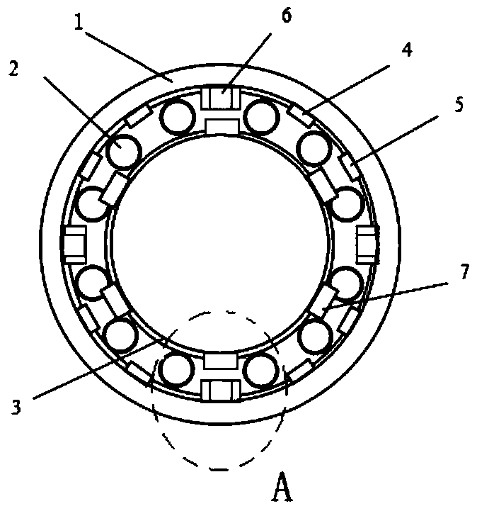
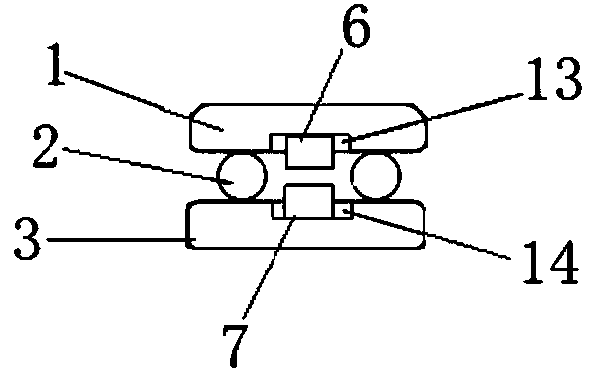
[0038] As shown in Figure 1-5, it is a schematic structural diagram of a preferred embodiment of a smart bearing with a built-in wireless sensor and self-powered function of the present invention, including: outer ring 1, roller 2, inner ring 3, and sensor components 4. Antenna 5, coil assembly 6, magnet 7, wherein:

[0039] As shown in Figure 1, the surface of the inner hole of the outer ring 1 avoids the position of the rollers 2, that is, the position between two rows of rollers 2, and an annul...


PUM


Abstract

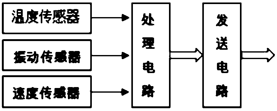
The invention provides an intelligent bearing internally provided with a wireless sensor and having a self-powered function. The intelligent bearing is provided with a sensor assembly, an antenna, a coil assembly and a magnet; an annular inner groove is formed in the inner surface of an outer ring, the sensor assembly, the antenna and the coil are arranged in the inner groove, an annular outer groove is formed in the outer surface of an inner ring, the magnet is arranged in the outer groove in a connected mode, the magnet rotates at a high speed along with the inner ring and generates magneticline cutting motion relative to the coil assembly, the inductive electric potential is generated in the coil assembly, and the coil assembly is connected with the sensor assembly and provides electric energy for the sensor assembly; the sensor assembly is used for collecting operation parameter information of the bearing and converting the collected information into data; and the sensor assemblyis connected with the antenna, the antenna is used for sending the data, and thus real-time monitoring of the bearing is achieved. The intelligent bearing does not need to be supplied with an externalpower supply, and real-time state monitoring of the bearing in the operation process is achieved through wireless transmission signals of a multi-parameter sensor.

Description

technical field [0001] The invention relates to an intelligent bearing, in particular to an intelligent bearing with a built-in wireless sensor and self-power supply function. Background technique [0002] Modern industry is gradually developing in the direction of specialization and refinement, and the market share of various high-end large-scale mechanical equipment is also increasing, which requires a commensurate maintenance strategy. In these large-scale equipment, the bearing becomes the most important core component and the "heart" of the equipment motion system. These large bearings are expensive to manufacture, and once damaged, the equipment will stop working, and even cause economic losses of millions or tens of millions. According to information, the failure rate of equipment caused by bearing damage is about 40% in the field of high-speed trains, about 40% in the field of large wind turbines, about 35% in the field of aero-engines, about 30% in the field of hea...

Claims


Application Information

Patent Timeline
IPC IPC(8): F16C19/02F16C33/58F16C33/30G01D21/02
CPCF16C19/02F16C33/30F16C33/58G01D21/02
Inventor 陶卫赵辉吕娜刘沅秩郑超陈潇李智
Owner SHANGHAI JIAO TONG UNIV
Learn More