A barrel type shock absorber

A shock-absorbing device, a barrel-type technology, applied in the direction of shock absorbers, springs/shock absorbers, shock absorbers, etc., can solve problems such as reducing mechanical use efficiency, loosening, equipment damage, etc., and achieve good results

Active Publication Date: 2021-05-18
HENAN UNIV OF SCI & TECH
View PDF7 Cites 0 Cited by
  • Summary
  • Abstract
  • Description
  • Claims
  • Application Information

AI Technical Summary

Problems solved by technology

However, when these machines are used in actual production, they will inevitably produce a large amount of mechanical vibration, impact, friction and other mechanical forces. At the same time, these mechanical vibrations have brought harm that cannot be underestimated.
For example, long-term mechanical vibration greatly reduces the fatigue strength of the machine, causing some mechanical components to be mechanically deformed due to the pressure of the vibration, or some bolt connections and other mechanisms on the machine are loosened by vibration, which reduces the mechanical strength. Use efficiency, even when reaching a certain resonant frequency, make the machine exceed its own bearing capacity and cause equipment damage, which will eventually endanger the driver's life and bring us immeasurable consequences

Method used


Image

  • A barrel type shock absorber
  • A barrel type shock absorber
  • A barrel type shock absorber

Examples


Embodiment 1

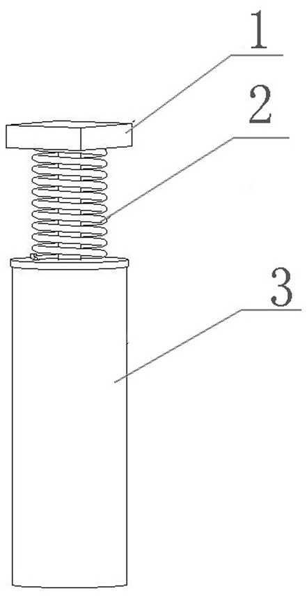
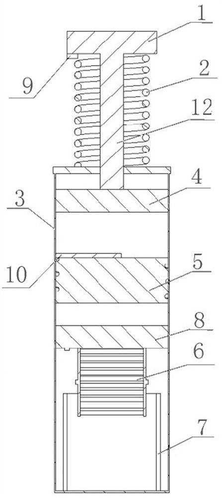
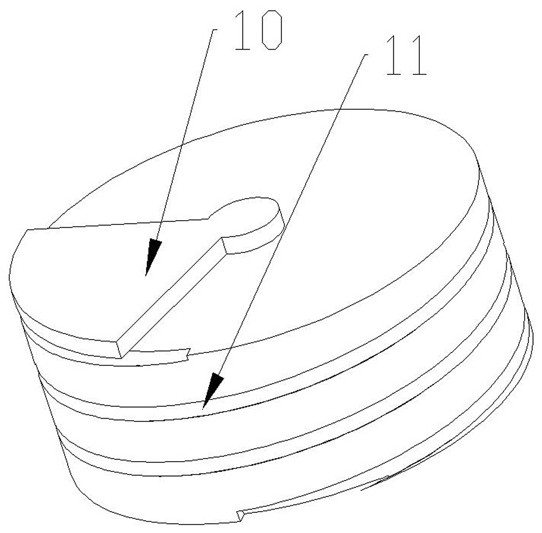
[0024] A cylindrical damping device, comprising a cylinder 3, a support plate 1, a SAW acceleration sensor 9, a shock absorbing spring 2, an upper piston 4, a middle partition 5, a lower piston 8, a conductor assembly 6 and a permanent magnet 7; The upper piston 4, the middle partition plate 5, the lower piston 8, the conductor assembly 6 and the permanent magnet 7 are all arranged in the cylinder 3; the upper piston 4 is supported by the piston rod 12 passing through the upper wall of the cylinder 3 The plate 1 is connected; the SAW acceleration sensor 9 is installed below the support plate 1; the shock absorbing spring 2 ring is arranged outside the piston rod 12 and is located between the support plate 1 and the upper wall of the cylinder 3; the middle partition 5 It is arranged below the upper piston 4, and the middle partition 5 is fixedly welded on the inner wall of the cylinder body 3; the middle partition 5 is provided with a spiral damping channel 11, and a stepping mo...


PUM


Abstract

The invention relates to a cylinder-type shock absorbing device, which belongs to the field of machinery. The device includes a cylinder body, a support plate, a SAW acceleration sensor, a shock-absorbing spring, an upper piston, a middle partition, a lower piston, a conductor assembly and a permanent magnet; the upper The piston is connected to the support plate through the piston rod; the SAW acceleration sensor is set under the support plate; the shock-absorbing spring ring is set outside the piston rod and between the support plate and the upper wall of the cylinder; the middle partition is welded on the inner wall of the cylinder; A damping channel is set on the middle partition, a stepping motor is set inside, and a damping adjustment plate is set on the top; the bottom of the lower piston is connected to a conductor assembly, which is connected to an external resistance through a wire; the conductor assembly is located in the magnetic field generated by the permanent magnet. The device can convert part of the mechanical energy into electric potential energy and consume it in the thermal energy of the metal conductor and the protective resistor, and convert the other part of the energy into the thermal energy between the hydraulic oil, the cylinder wall and the damping channel, thereby realizing three-part shock absorption, making the vibration The effect is more efficient.

Description

technical field [0001] The invention belongs to the field of machinery, and in particular relates to a cylinder type damping device. Background technique [0002] With the continuous development and popularization of agricultural mechanization in our country, more and more agricultural machinery has been put into production and application. However, when these machines are used in actual production, they will inevitably produce a large amount of mechanical vibration, impact, friction and other mechanical forces. At the same time, these mechanical vibrations have brought harm that cannot be underestimated. For example, long-term mechanical vibration greatly reduces the fatigue strength of the machine, causing some mechanical components to be mechanically deformed due to the pressure of the vibration, or some bolt connections and other mechanisms on the machine are loosened by vibration, which reduces the mechanical strength. The use efficiency, even when reaching a certain r...

Claims


Application Information

Patent Timeline
Patent Type & Authority Patents(China)
IPC IPC(8): F16F13/06F16F9/19F16F9/32F16F9/34F16F6/00
CPCF16F6/005F16F9/19F16F9/3207F16F9/34F16F13/06
Inventor 庞靖周罕觅戴宝琼张志毅曹亚州赵赫陈凯康
Owner HENAN UNIV OF SCI & TECH
Why Eureka
Try Eureka