Improved boiler separator

A separator and improved technology, applied in the field of separators, can solve the problems of reduced flow rate and easy wear of boiler separator inlet, and achieve the effect of increasing feed flow rate, high wear resistance coefficient and reducing inlet area

Inactive Publication Date: 2019-04-16
JIANGSU LEE & MAN PAPER MFG
View PDF5 Cites 0 Cited by
  • Summary
  • Abstract
  • Description
  • Claims
  • Application Information

AI Technical Summary

Problems solved by technology

[0003] The purpose of the present invention is to provide an improved boiler separator to solve the technical problems that the inlet of the boiler separator is easy to wear and the flow rate is reduced

Method used


Image

  • Improved boiler separator
  • Improved boiler separator
  • Improved boiler separator

Examples


Embodiment Construction

[0024] In order to make the technical means, creative features, goals and effects achieved by the present invention easy to understand, the present invention will be further elaborated below in conjunction with specific embodiments, but the following embodiments are only preferred embodiments of the present invention, not all. Based on the examples in the implementation manners, other examples obtained by those skilled in the art without making creative efforts all belong to the protection scope of the present invention.

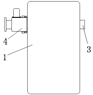
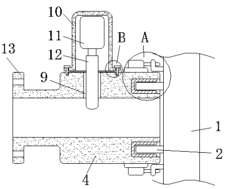
[0025] Such as Figure 1-4 As shown, an improved boiler separator includes a body 1. The body 1 is provided with an inlet 2 and an outlet 3. The outside of the inlet 2 is coaxially provided with a cylinder 4. The cylinder 4 is made of wear-resistant materials. The cylinder 4 A flange 13 is coaxially fixed at the end away from the inlet 2, and the flange 13 and the barrel 4 are of an integrated structure.

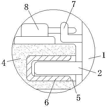
[0026] The end of cylinder body 4 close to inlet 2 ...


PUM


Abstract

The invention discloses an improved boiler separator which comprises a main body, wherein the main body is provided with an inlet and an outlet; a cylinder is coaxially arranged outside the inlet andmade of an abrasion-resistant material; a ring-shaped groove is coaxially formed in the end, close to the inlet, of the cylinder; the inlet is clamped into the ring-shaped groove in a clamping manner;a guiding hole is formed in the side wall of the cylinder; a shell is arranged at the opening of the guiding hole and fixed on the side wall of the cylinder; a hydraulic pump is fixed on the inner top wall of the shell; and a limiting plate is fixed at the extending end of the hydraulic pump and movably inserted into the guiding hole. By the adoption of the improved boiler separator disclosed bythe invention, the feed flow rate can be effectively improved, and then the separating efficiency can be improved.

Description

technical field [0001] The invention relates to a separator, in particular to an improved boiler separator. Background technique [0002] During the use of the inlet of the boiler separator, the thickness will continue to decrease with the friction of the material, thereby increasing the area of ​​the inlet and reducing the flow rate of the material passing through the inlet, thereby reducing the separation efficiency of the boiler separator. When the separation efficiency of the circulating fluidized bed boiler separator decreases, that is, the load capacity and desulfurization capacity of the boiler decrease, thereby reducing the material circulation rate, which in turn leads to an increase in plant energy consumption and a direct increase in operating costs. Contents of the invention [0003] The purpose of the present invention is to provide an improved boiler separator to solve the technical problems that the inlet of the boiler separator is easy to wear and the flow ...

Claims


Application Information

Patent Timeline
Patent Type & Authority Applications(China)
IPC IPC(8): F23C10/18B01D46/00
Inventor 李文斌
Owner JIANGSU LEE & MAN PAPER MFG
Why Eureka
Try Eureka