

Overcurrent fault diagnosis system, method and train
An overcurrent fault diagnosis system technology, applied in the direction of measuring current/voltage, measuring devices, instruments, etc., can solve problems affecting the operation safety of EMUs, difficult faults, and failure to diagnose and locate high-voltage bus overcurrent faults, etc., to achieve The effect of improving diagnosis and processing efficiency, improving safety, and facilitating timely processing of faults
- Summary
- Abstract
- Description
- Claims
- Application Information
AI Technical Summary
Problems solved by technology
Method used
Image

Examples
no. 1 example
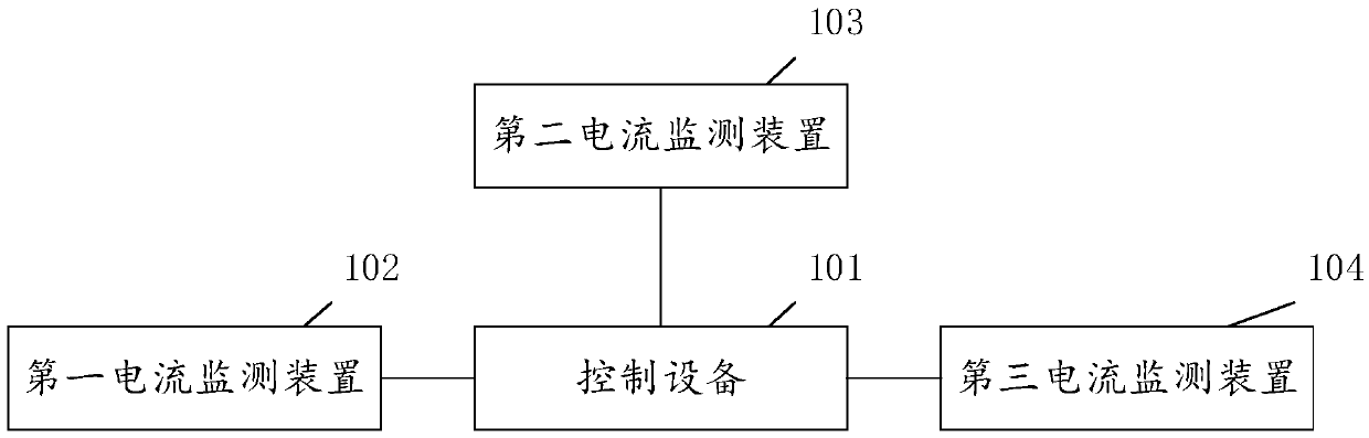
[0039] see figure 1 , which is a schematic structural diagram of an overcurrent fault diagnosis system provided in this embodiment.
[0040] Such as figure 1 As shown, the overcurrent fault diagnosis system provided in this embodiment includes: a control device 101 , a first current monitoring device 102 , a second current monitoring device 103 and a third current monitoring device 104 .
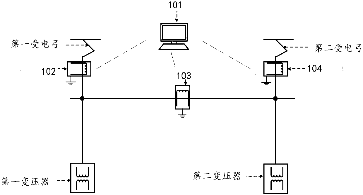
[0041] see figure 2 , which is a schematic diagram of the circuit connection of the overcurrent fault diagnosis system. Such as figure 2 As shown, the first current monitoring device 102 , the second current monitoring device 103 and the third current monitoring device 104 are respectively connected to the control device 101 in communication. The first current monitoring device 102 is located on the main road where the first pantograph is located; the second current monitoring device 103 is located on the branch from the first pantograph to the second transformer and the branch from th...
no. 2 example
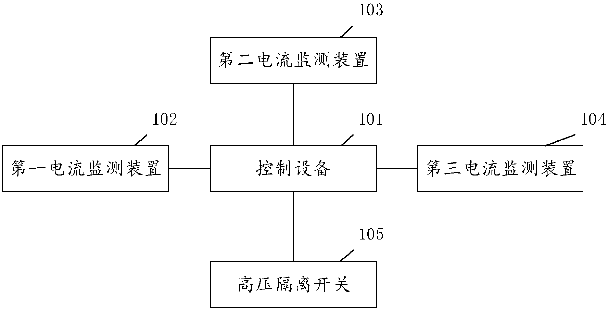
[0053] see image 3 , which is a schematic structural diagram of an overcurrent fault diagnosis system provided in this embodiment.
[0054] Such as image 3 As shown, the overcurrent fault diagnosis system provided in this embodiment includes: a control device 101 , a first current monitoring device 102 , a second current monitoring device 103 , a third current monitoring device 104 and a high voltage isolation switch 105 .
[0055] see Figure 4 , which is a schematic circuit connection diagram of the overcurrent fault diagnosis system provided in this embodiment. Such as Figure 4 As shown, the first current monitoring device 102, the second current monitoring device 103, the third current monitoring device 104, and the high-voltage isolation switch 105 are respectively connected to the control device 101 in communication; the first current monitoring device 102 is located at the place where the first pantograph is located. On the main road; the second current monitorin...
no. 3 example
[0077] see Figure 5 , which is a flow chart of the method for diagnosing an overcurrent fault provided in this embodiment.
[0078] Such as Figure 5 As shown, the overcurrent fault diagnosis method provided in this embodiment includes:
[0079] S501: When the first pantograph is in the working state, judge whether an overcurrent fault has occurred in the main circuit where the first pantograph is located based on the first current result collected by the first current monitoring device, and determine whether an overcurrent fault has occurred on the main circuit where the first pantograph is located, and use the first current result collected by the second current monitoring device The second current result judges whether an overcurrent fault occurs in the common branch of the branch from the first pantograph to the second transformer and the branch from the second pantograph to the first transformer; the first current monitoring device is located at the first The main road...
PUM
 Abstract
Description
Claims
Application Information