A voltage transient signal detection circuit and method based on FPGA
A voltage transient and signal detection technology, applied in the direction of measuring electrical variables, measuring current/voltage, measuring devices, etc., can solve problems such as slow detection speed, voltage transient leakage detection, and increased CPU system burden, achieving fast speed, The effect of high portability
- Summary
- Abstract
- Description
- Claims
- Application Information
AI Technical Summary
Problems solved by technology
Method used
Image
Examples
Embodiment 1
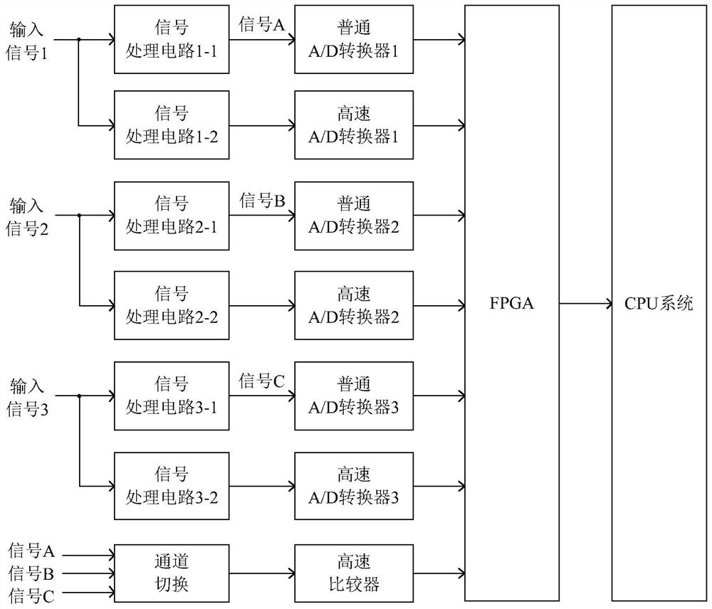
[0065] Such as figure 1 As shown, a voltage transient signal detection circuit based on FPGA has 3 voltage input signals. After the 3 voltage input signals pass through the signal processing circuit, they are sent to the frequency measurement circuit. The frequency measurement circuit is composed of a channel switching circuit and a high-speed Composed of comparators, the channel switching circuit sends the 3-way input signal to the high-speed comparator in turn according to the switching clock set by the FPGA. After being converted into a digital signal by the high-speed comparator, it is sent to the FPGA to complete the 3-way input. Signal frequency measurement function.
[0066] It has 3 voltage input signals, each input signal includes 2 channels, the first channel is composed of signal processing circuit and ordinary A / D converter, used for voltage slow transient signal acquisition, and the second channel is composed of signal processing circuit The circuit and high-spee...
Embodiment 2
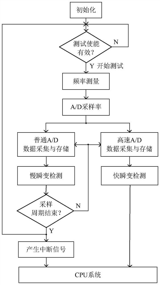
[0069] On the basis of the above-mentioned embodiment 1, the present invention also provides a method for realizing voltage transient signal detection based on FPGA, the process of which is as follows figure 2 As shown, the specific steps are as follows:
[0070] Step 1: Perform initialization work, including normal A / D converter initialization, high-speed A / D converter initialization, acquisition status bit clearing and transient register reset;
[0071] Step 2: Wait for the test enable signal sent by the CPU system to the FPGA. If the test enable signal is valid, start the test and continue to execute, otherwise wait until the test enable signal is valid;
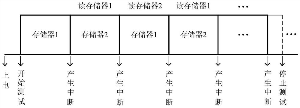
[0072] Step 3: Execute the frequency measurement function; the channel switching circuit sends the 3-way voltage input signal to the high-speed comparator in turn according to the switching clock set by the FPGA, and after converting it into a digital clock signal, complete the 3-way voltage input in the FPGA Signal fre...
PUM
 Abstract
Description
Claims
Application Information
 - R&D
- Intellectual Property
- Life Sciences
- Materials
- Tech Scout
- Unparalleled Data Quality
- Higher Quality Content
- 60% Fewer Hallucinations
Browse by: Latest US Patents, China's latest patents, Technical Efficacy Thesaurus, Application Domain, Technology Topic, Popular Technical Reports.
© 2025 PatSnap. All rights reserved.Legal|Privacy policy|Modern Slavery Act Transparency Statement|Sitemap|About US| Contact US: help@patsnap.com


