
Bracket for core module and solid state battery module structure

A battery module and battery module technology, applied to battery pack parts, secondary batteries, structural parts, etc., can solve problems such as difficulty in meeting market needs, volumetric energy density and volume density limitations, and improve thermal management Efficiency, enhanced heat transfer effect, and reduced production cost

Pending Publication Date: 2019-04-16
WM MOTOR TECH GRP CO LTD
View PDF0 Cites 4 Cited by
  • Summary
  • Abstract
  • Description
  • Claims
  • Application Information

AI Technical Summary

Problems solved by technology

However, liquid lithium battery liquid is facing the problem of volume energy density and volume density limitations, and it has been difficult to meet market needs.

Method used


Image

  • Bracket for core module and solid state battery module structure
  • Bracket for core module and solid state battery module structure
  • Bracket for core module and solid state battery module structure

Examples


Embodiment 1

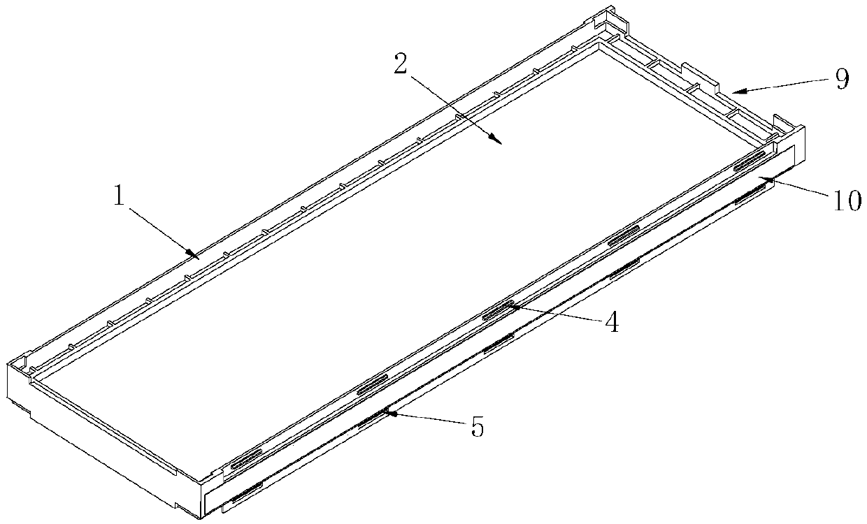
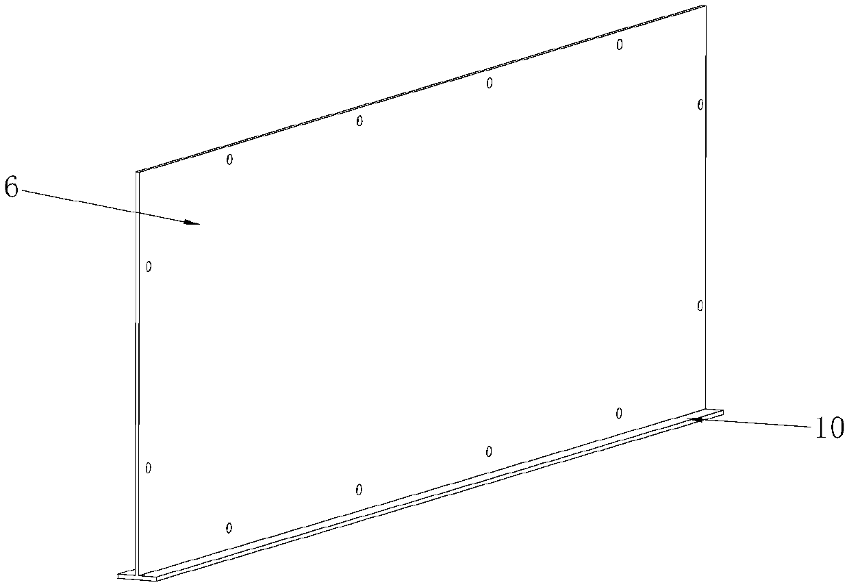
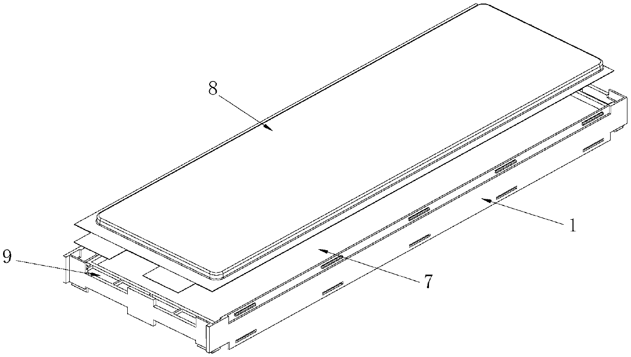
[0031] Such as Figure 1~5 The shown bracket for the cell module includes a frame body 1 made of plastic. The outer contour of the frame body 1 is rectangular, and a through hole 2 with a rectangular shape is formed in the middle of the frame body 1. The through hole 2 It runs through the entire frame body 1 along the thickness direction of the frame body 1 . The bottom of the frame main body 1 is provided with a cooling groove 3, and on both sides of the frame main body 1, a number of bracket buckles 4 and bracket snap holes 5 that can form mutual cooperation are provided on the bottom frame of the frame main body 1. 4 and bracket clamping holes 5 are respectively arranged on both sides of the heat sink 3 . In addition, a number of bracket buckles 4 and bracket buckle holes that can be formed to cooperate with each other are also arranged on the frame at the top of the frame body 1 .

[0032] A heat dissipation aluminum sheet 6 as a heat dissipation fin is integrally formed...

Embodiment 2

[0037] Such as Figure 6-8 The solid-state battery module structure shown includes an upper case 11 and a lower case 12. The upper case 11 and the lower case 12 are mutually covered to form a cavity in which several cell modules 13 are installed. The cell module body formed by splicing each other is provided with a thermally conductive rubber pad 14 between the lower case 12 and the battery module body. The cell module 13 includes a cell bracket 15, the cell bracket 15 is designed to use the bracket for the cell module in Embodiment 1, the bracket buckle 4 of the cell bracket 15 is connected to the bracket button hole of the adjacent cell bracket 15 In combination, multiple cell modules 13 can be spliced ​​together. In the cell support 15 , the cell 8 is attached to the cell heat dissipation area 7 , and the heat dissipation rib portion 10 is attached to the rubber pad 14 . On both sides of the cell module body, side brackets 16 are installed on the cell module body to fix t...


PUM


Abstract

The invention discloses a bracket for a core module. In particular, the bracket comprises a frame main body, wherein a through hole is formed in the frame main body; a heat sink is arranged inside theframe main body; a core heat dissipation region exposed via the through hole is formed on the heat sink; the bottom of the frame main body is also provided with heat dissipation slots with slot widthextending to both sides of the heat sink; the heat sink is communicated into the heat dissipation slots and extends to the inner walls of the heat dissipation slots to form a radiation rib covering the whole heat dissipation slots; and the frame body is also provided with polar earholes around the through hole. The invention also discloses a solid-state battery module structure using the bracketfor the core module. The bracket has the advantages of excellent core heating and cooling effects, uniform thermal field of the battery module, convenience in assembly, and easy assembly of the solid-state battery module.

Description

technical field [0001] The invention relates to a power battery, in particular to a battery cell module bracket and a solid-state battery module structure. Background technique [0002] With the depletion of global resources and the deterioration of the environment, electric vehicles have developed rapidly, and the power batteries used in electric vehicles are also constantly being updated and developed. At present, in the competition of various power battery design technology routes, the pure electric technology route mainly based on liquid lithium batteries is the mainstream of the market. However, liquid lithium battery liquid is facing the problem of volume energy density and volume density limitations, and it has been difficult to meet market needs. [0003] The solid-state lithium battery is a power battery design that replaces the diaphragm and electrolyte with a solid electrolyte. The thickness and weight of this battery can be greatly reduced. Therefore, solid-stat...

Claims


Application Information

Patent Timeline
Patent Type & Authority Applications(China)
IPC IPC(8): H01M2/10H01M10/613H01M10/625H01M10/655H01M10/6551H01M10/6554H01M50/249
CPCH01M10/613H01M10/625H01M10/655H01M10/6551H01M10/6554H01M50/20Y02E60/10
Inventor 贾倩
Owner WM MOTOR TECH GRP CO LTD
Learn More