Concentrating photovoltaic device with temperature control function

A concentrating photovoltaic and equipment technology, applied in the field of photovoltaic equipment, can solve the problems of reducing the photoelectric conversion efficiency and service life of photovoltaic panels, affecting the photoelectric conversion efficiency of photovoltaic panels, and reducing the light receiving rate of photovoltaic panels, so as to improve photoelectric conversion efficiency and improve Heat dissipation effect, the effect of accelerating heat dissipation

Inactive Publication Date: 2019-04-16
CHANGSHA XIAORU INFORMATION TECH CO LTD
View PDF10 Cites 3 Cited by
  • Summary
  • Abstract
  • Description
  • Claims
  • Application Information

AI Technical Summary

Problems solved by technology

However, only part of the solar energy incident on the photovoltaic panel is converted into electrical energy, and the rest is converted into thermal energy and stored in the photovoltaic panel. The heat accumulated in the battery will degrade the performance of the photovoltaic battery, reducing the photoelectric conversion efficiency and usage of the photovoltaic panel. life
[0003] At present, the commonly used heat dissipation method is to directly spray cold water on the photovoltaic panel to cool down. Although this method can achieve a cooling effect, long-term water spray cooling treatment will easily form water stains on the surface of the photovoltaic panel, which will block the light and reduce the temperature of the photovoltaic panel. The light receiving rate affects the photoelectric conversion efficiency of photovoltaic panels

Method used


Image

  • Concentrating photovoltaic device with temperature control function
  • Concentrating photovoltaic device with temperature control function
  • Concentrating photovoltaic device with temperature control function

Examples


Embodiment Construction

[0024] The embodiments of the present invention will be described in detail below with reference to the accompanying drawings, but the present invention can be implemented in various ways defined and covered by the claims.

[0025] In order to make the purpose, technical solutions and advantages of the embodiments of the present invention clearer, the technical solutions in the embodiments of the present invention will be clearly and completely described below in conjunction with the drawings in the embodiments of the present invention. Obviously, the described embodiments It is a part of embodiments of the present invention, but not all embodiments. Based on the embodiments of the present invention, all other embodiments obtained by persons of ordinary skill in the art without creative efforts fall within the protection scope of the present invention.

[0026] The following will clearly and completely describe the technical solutions in the embodiments of the present inventio...


PUM


Abstract

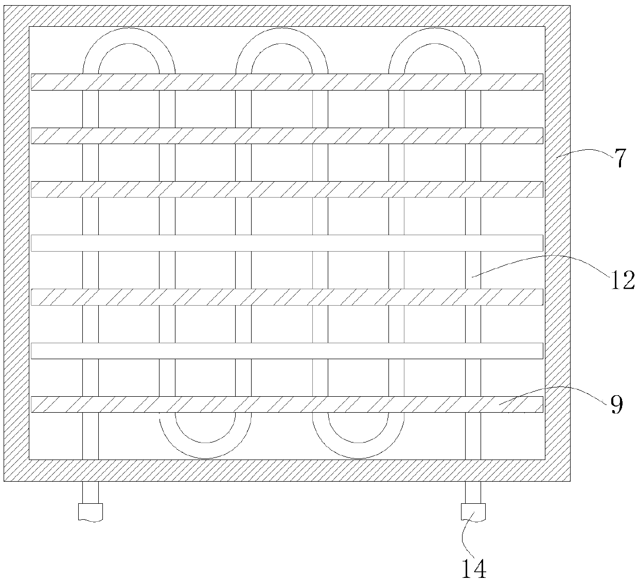
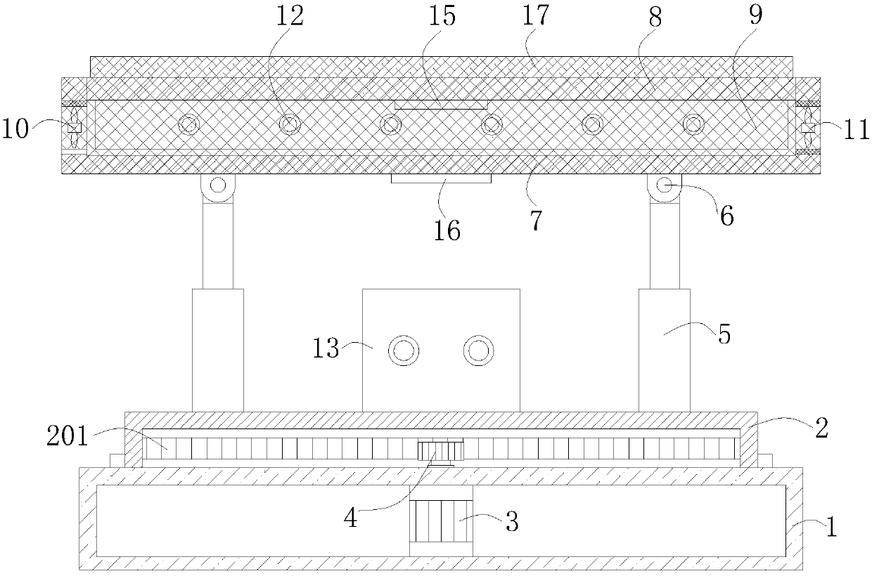
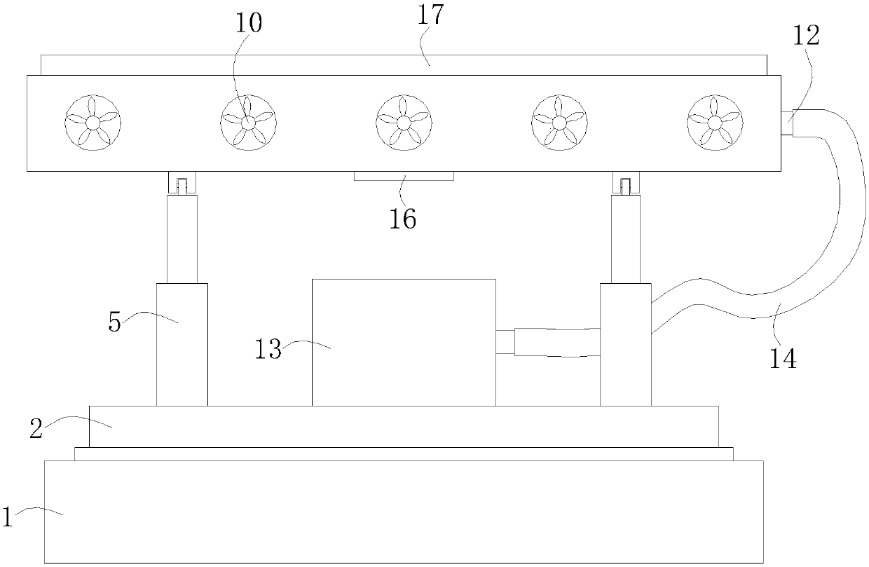
The invention relates to the technical field of photovoltaic devices, in particular to a concentrating photovoltaic device with a temperature control function. The concentrating photovoltaic device includes a base and a photovoltaic plate. The top of the base is rotatably connected with a rotating disk, and the inner wall of the rotating disk is provided with a ring of inner gear teeth; a motor isarranged in the base; and an output shaft of the motor runs through the top of the base, a gear is connected to the output shaft of the motor, and the gear meshes with the inner gear teeth. The leftand right ends of the top of the rotating disc are respectively provided with electric telescopic rods, and the top of the electric telescopic rods are connected to movable connecting members, and thetops of the movable connecting members are connected with a fixing frame. The concentrating photovoltaic device is novel in design and is convenient to use. The concentrating photovoltaic device caneffectively prevent light from being blocked due to the formation of water stains on the surface of the photovoltaic panel while effectively cooling the photovoltaic panel; In addition, the concentrating photovoltaic device can also realize the adjustment of the orientation and inclination of the photovoltaic panel, so that the photovoltaic panel can fully receive the sunlight, and the photoelectric conversion efficiency of the photovoltaic panel is improved.

Description

technical field [0001] The invention relates to the technical field of photovoltaic equipment, in particular to a concentrated photovoltaic equipment with a temperature control function. Background technique [0002] Solar concentrating photovoltaic technology (CPV) is an effective way to reduce the cost of photovoltaic power generation. It combines optical technology with new energy, greatly increases the power generation of photovoltaic panels, and continuously improves efficiency. Optical components such as lenses or mirrors are used , Converge a large area of ​​sunlight into a very small area, and then directly convert it into electricity through high-conversion photovoltaic panels. However, only a part of the solar energy incident on the photovoltaic panel is converted into electrical energy, and the rest is converted into thermal energy and stored in the photovoltaic panel. The heat accumulated in the battery will degrade the performance of the photovoltaic battery, re...

Claims


Application Information

Patent Timeline
Patent Type & Authority Applications(China)
IPC IPC(8): H02S20/30H02S40/42
CPCH02S20/30H02S40/425Y02E10/50
Inventor 不公告发明人
Owner CHANGSHA XIAORU INFORMATION TECH CO LTD
Why Eureka
Try Eureka