Mixer-settler

A technology of mixing and settling tanks and settling tanks, which is applied in the field of liquid-liquid extraction, can solve the problems of low mass transfer efficiency and achieve the effect of improving mass transfer efficiency

Active Publication Date: 2019-04-19
CHINA NUCLEAR POWER ENG CO LTD
View PDF7 Cites 2 Cited by
  • Summary
  • Abstract
  • Description
  • Claims
  • Application Information

AI Technical Summary

Problems solved by technology

Therefore, the mass transfer efficiency of the existing mixing...

Method used


Image

  • Mixer-settler
  • Mixer-settler
  • Mixer-settler

Examples


Embodiment 1

[0053] This embodiment provides a mixing and clarification tank, comprising: at least one clarification tank, the clarification tank includes: a mixing chamber, a clarification chamber, and a separation chamber arranged and communicated in sequence, and the clarification tank also includes: a submerged chamber arranged below the mixing chamber The separation chamber includes: a heavy phase chamber and a light phase chamber. The light phase and heavy phase enter the mixing chamber to be mixed into a mixed phase, and then sent to the clarification chamber. The clarification chamber is used to separate the mixed phase into a light phase and a heavy phase. and sent to the light phase chamber and the heavy phase chamber respectively in the separation chamber, and flow out of the clarification tank from the light phase chamber and the heavy phase chamber; The phase or light phase flows into the return chamber, one end of the return pipe is connected to the submerged chamber, and the ...

Embodiment 2

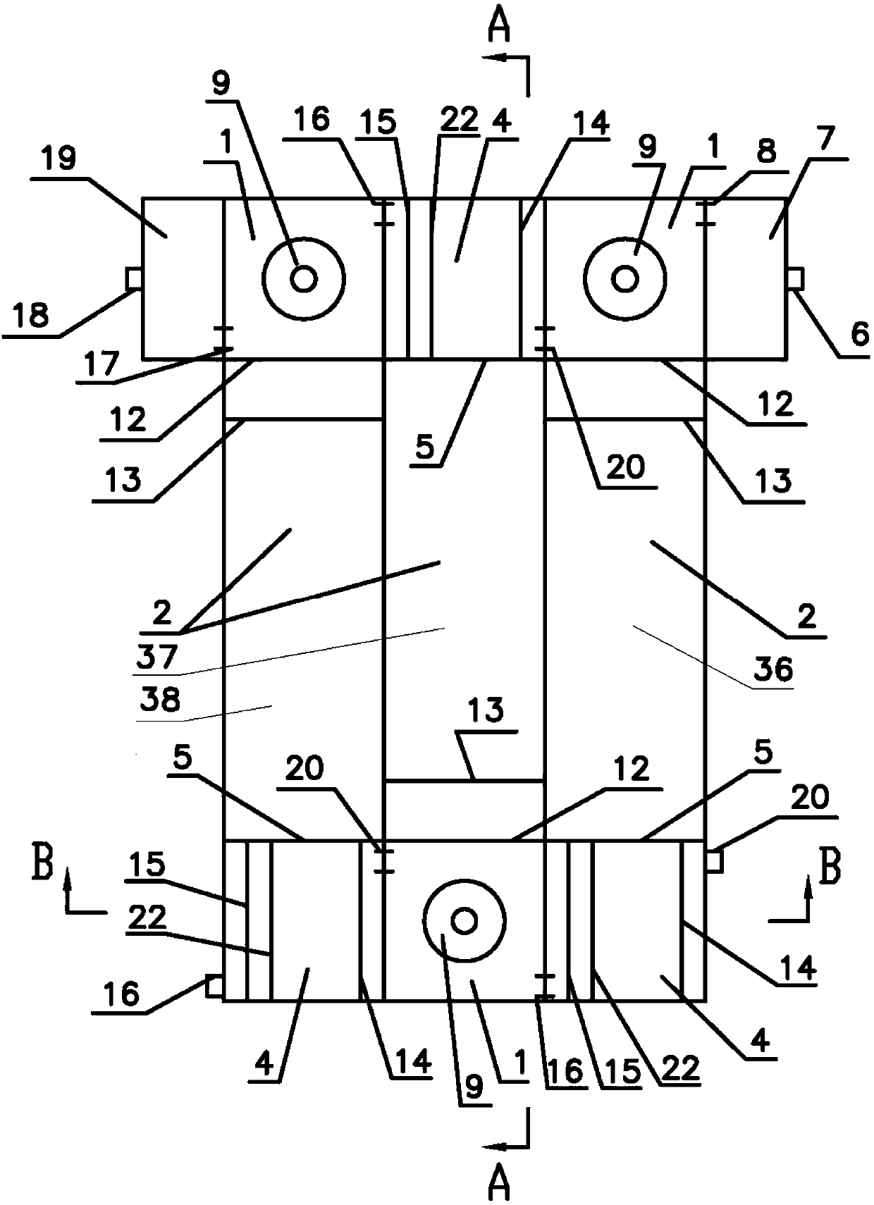
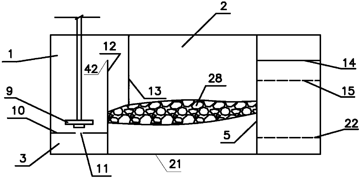
[0059] Such as Figure 1-7 As shown, the present embodiment provides a mixing and clarification tank, including: at least one clarification tank, the clarification tank includes: a mixing chamber 1, a clarification chamber 2, and a separation chamber 4 arranged in sequence and communicated, and the clarification tank also includes: 1 below and communicated with the submerged chamber 3, the separation chamber 4 includes: a heavy phase chamber 35, a light phase chamber 34, the light phase and the heavy phase enter the mixing chamber 1 to be mixed into a mixed phase, and then are transported to the clarified chamber 2, clarified chamber 2. It is used to separate the mixed phase into light phase and heavy phase, and send them into the light phase cell 34 and the heavy phase cell 35 respectively in the separation chamber 4, and flow out of the clarifier from the light phase cell 34 and the heavy phase cell 35; Chamber 4 also includes: a reflux chamber, and the mixing and clarificat...

Embodiment 3

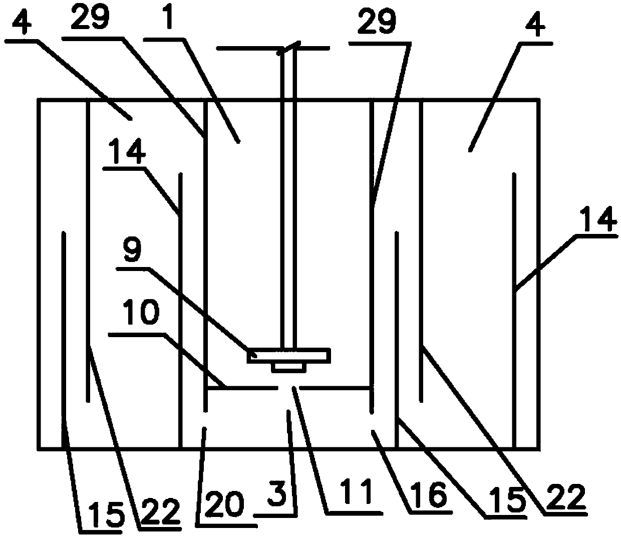
[0108] Such as Figure 8 , 9 As shown, this embodiment provides a mixing and settling tank, and the difference from the mixing and settling tank in Example 2 is: the return pipeline includes: heavy phase return pipeline 26, and the return chamber includes: heavy phase return chamber 32, inside the separation chamber 4 The heavy phase of the heavy phase flows into the heavy phase reflux chamber 32, one end of the heavy phase reflux pipeline 26 is connected with the heavy phase reflux chamber 32, and the other end of the heavy phase reflux pipeline 26 is connected with the submerged chamber 3, when the light phase flow in the mixing and settling tank is greater than Heavy phase flow, the heavy phase return pipeline 26 is used to return the heavy phase back to the submerged chamber 3 . The connection between the heavy phase return pipeline 26 and the heavy phase return chamber 32 is close to the bottom plate 33 of the heavy phase return chamber. Specifically, the structure of t...


PUM


Abstract

The invention discloses a mixer-settler which comprises at least one settling tank. The settling tank comprises a mixing chamber, a settling chamber and a separation chamber which are sequentially arranged and communicated. The settling tank also comprises a submersible chamber which is arranged below the mixing chamber and communicated with the mixing chamber. The separation chamber comprises a heavy phase chamber, a light phase chamber, and the separation chamber also comprises a reflux chamber, wherein the heavy phase or the light phase in the separation chamber flows into the reflux chamber. One end of a reflux pipeline is connected with the submersible chamber and the other end of the reflux pipeline is connected with the reflux chamber. The reflux pipeline is used for refluxing the heavy phase or the light phase back to the submersible chamber. Under the condition that the two-phase flow of the heavy phase and the light phase in the mixer-settler is relatively large, a part of one phase with a smaller flow rate can be refluxed into the mixing chamber, so that the contact phase ratio of the two phases in the mixing chamber is close to 1, and the mass transfer efficiency is improved.

Description

technical field [0001] The invention belongs to the technical field of liquid-liquid extraction, and in particular relates to a mixing and settling tank. Background technique [0002] The stirring device of the pump wheel type mixing and settling tank not only plays the role of two-phase mixing and stirring, but also can transport single-phase or two-phase materials, so the pump wheel type mixing and settling tank can be enlarged and designed in a wide flow range without improving the stage efficiency. will decrease. [0003] In the liquid-liquid extraction process, in order to reduce the amount of light phase or heavy phase material, or to reduce the amount of waste liquid generated, or to achieve the purpose of concentrating the extracted substance, it is usually necessary to use a relatively large flow ratio (the phase with larger flow rate The ratio of the flow of the phase to the flow of the other phase). In general, when fully mixed, the contact ratio of the two phas...

Claims


Application Information

Patent Timeline
IPC IPC(8): B01D11/04
CPCB01D11/04B01D11/0446B01D11/0457
Inventor 刘继连李思凡刘郢陈勇苑斯雯熊佳丽李硕李磊
Owner CHINA NUCLEAR POWER ENG CO LTD
Why Eureka
Try Eureka