Rotary type flue gas demister
A rotary, mist eliminator technology, applied in chemical instruments and methods, dispersed particle filtration, transportation and packaging, etc., can solve the problems of dust emission, no mist adsorption, mist removal efficiency and effect are not very good, etc., Achieve good defogging effect and high efficiency
- Summary
- Abstract
- Description
- Claims
- Application Information
AI Technical Summary
Problems solved by technology
Method used
Image

Examples
Embodiment 1
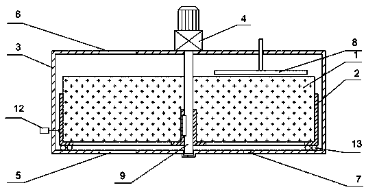
[0018] combine figure 1 , image 3 and Figure 4 , the present invention is described as follows:
[0019] The rotary flue gas demister is composed of bracket 1, box shell 2, power unit 4 and demist body 3. The material of demist body 3 is EVA sponge, which is made into a circle corresponding to the cavity of bracket 2. The casing 2 is a cylindrical casing, and a power unit 4 is installed on the upper part of the casing. The power unit 4 is composed of an electric motor and a transmission. The rotating shaft 9 connected with the transmission extends into the interior of the casing 2. Outside the air port 6 and the water outlet hole 7, the inside of the box shell 2 is a circular airtight cavity, and the defogging body 3 is placed in the cavity. Bracket 1 is keyed to rotating shaft 9 and is fixed along the circumference of shaft 9. Rolling bearing 13 is installed at the bottom of bracket 1. Guide rails are set at the corresponding positions of box shell 2. Rotate together; t...
Embodiment 2
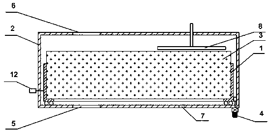
[0022] The difference from Embodiment 1 is that the power unit 4 is not arranged in the central part of the box shell 2, but is set on the outside of the box shell 2, and the rotating shaft 9 is not provided, combined with figure 2 and image 3 , the present invention is described as follows:
[0023] The rotary flue gas demister is composed of bracket 1, box shell 2, power unit 4 and demister 3. The material of demister 3 is EVA sponge, except that it is provided with air inlet 5, air outlet 6 and water outlet. 7, the inside of the box shell 2 is a circular airtight cavity, and the defogger 3 and the bracket 1 are placed in the cavity. The defogger 3 is a whole piece or spliced into a disc shape, placed on the bracket 1, The outer edge of the frame 1 has gear teeth, which mesh with the gears on the reducer. The power device 4 is installed outside the box shell 2. The power is transmitted to the bracket 1 through the gears on the reducer, driving the bracket 1 to rotate, a...
Embodiment 3
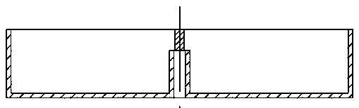
[0026] combine figure 1 , image 3 and Figure 4 , the present invention is described as follows:
[0027] The rotary flue gas demister is composed of a bracket 1, a box shell 2, a power unit 4 and a mist removal body 3. The material of the mist removal body 3 is EVA sponge, and the box shell 2 is a cylindrical shell. The power unit 4 is installed. The power unit 4 is composed of a motor and a transmission. The rotating shaft 9 connected with the transmission extends into the inside of the case shell 2. Except that the air inlet 5, the air outlet 6 and the water outlet 7 are provided, the inside of the case case 2 is a Circular airtight cavity, the defogger 3 and the bracket 1 are placed in the cavity, the defogger 3 is placed on the bracket 1; the bracket 1 is provided with ribs 11 along a diameter line, and the ribs 11 empty the bracket 1 The cavity is divided into two semicircles, and correspondingly, the shape of the demisting body 3 is also a semicircle; the bracket 1 ...
PUM
 Abstract
Description
Claims
Application Information