
Device and method for decomposing liquid chemical weapons under microwave irradiation

A chemical weapon and microwave generating device technology is applied in the field of devices for decomposing liquid chemical weapons under microwave irradiation to achieve the effect of avoiding leakage

Active Publication Date: 2020-03-20
SHANDONG UNIV
View PDF4 Cites 0 Cited by
  • Summary
  • Abstract
  • Description
  • Claims
  • Application Information

AI Technical Summary

Problems solved by technology

However, the assessment of these alternative technologies in the United States is that incineration is still the preferred destruction technology. These alternative technologies are still in the process of exploratory testing and evaluation, and there is still a certain distance from practical application.

Method used


Image

  • Device and method for decomposing liquid chemical weapons under microwave irradiation
  • Device and method for decomposing liquid chemical weapons under microwave irradiation
  • Device and method for decomposing liquid chemical weapons under microwave irradiation

Examples


Embodiment 1

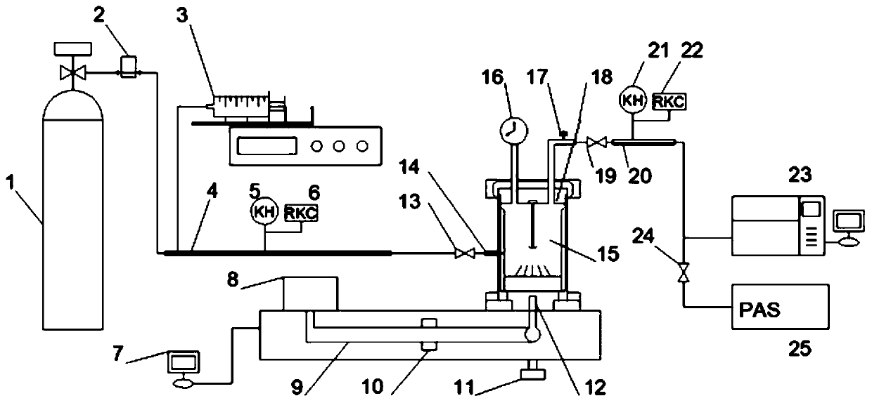
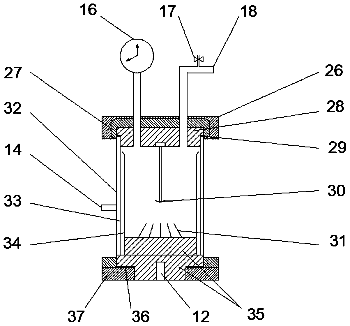
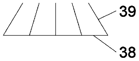
[0057] A device for decomposing liquid chemical weapons under microwave irradiation, comprising a gas cylinder 1, an automatic injector 3, a reactor 15, and a microwave generating device. The gas cylinder 1 is connected to the air inlet 14 of the reactor 15 through an air inlet pipe, The pipeline is provided with a first heating belt 4, and the automatic injector 3 is connected to the part covered by the first heating belt 4 of the air intake pipeline. The first heating belt 4 is an electric heat tracing device located on the wall of the air intake pipeline, and the automatic injector 3 inputs poison liquid. The poison liquid and the carrier gas input by the gas cylinder 1 are mixed in the intake pipe and heated by the first heating belt 4 to become a gas that enters the reactor 15. The lower part of the cavity of the reactor 15 is provided with a discharger 31, and the discharger 31 It consists of a support and several discharge metal wires. The upper side of the support is fi...

Embodiment 2

[0083] Using the above device to measure the interactive discharge process of microwave and medium under multi-physics field, the process is as follows:

[0084] Take wire tungsten as the target material, put the wire into the quartz lining 34, seal the reactor 15, open the third shut-off valve 13, close the fourth shut-off valve 17, open the first shut-off valve 19, and open the gas cylinder 1 valve Put in the carrier gas for 2 minutes, turn on the water load 10 to carry out water circulation, set the microwave power to 900W, turn on the microwave preheating, and then turn on the microwave generator. After the microwave works for 1 minute, you can hear the crackling sound of metal discharge. After 2 minutes, wait for the metal to discharge When it tends to be stable, close the first cut-off valve 19, open the automatic injector 3 and the first heating belt 4, and set different carrier gas flow rates and poison flow rates for different poisons, so that the poisons can be comple...


PUM

PropertyMeasurementUnit
diameteraaaaaaaaaa

Abstract

The invention relates to a device and method for decomposing a liquid chemical weapon under microwave radiation. The device comprises a gas bottle, an automatic injection device, a reactor and a microwave generation device. Carrier gas and a toxicant enter the reactor through the gas bottle and the automatic injection device respectively, the reactor comprises a top cover, a stirring rod, a discharger and a pad block, and the top cover is located on the upper portion of the reactor; the top of the stirring rod is fixedly connected with the bottom of the top cover, the discharger is composed ofa supporting base and multiple discharging metal wires, and the upper side of the supporting base is fixedly connected with one end of each discharging metal wire; the discharging metal wires are vertically placed, the base is located at the bottom of the reactor, and the discharger is located on the base; the supporting base is located on the upper surface of the base, and one end of the microwave generation device is located below the base. The discharger is located in the center of the base, and the other end of each discharging metal wire points to the center of the bottom of the stirringrod. Under the cooperation effect of microwaves and metal discharging, the toxicant is subjected to pyrolysis and oxidized, and the aim of treating toxicant liquid is achieved.

Description

technical field [0001] The invention belongs to the technical field of environmental protection, and in particular relates to a device and method for decomposing liquid chemical weapons under microwave irradiation. Background technique [0002] Chemical weapons are a general term for various weapons and equipment that kill humans, animals, and plants with poisons. The basis of chemical weapons is chemical poisons. Conventional weapons are used in warfare to disperse poisons into steam, liquid droplets, aerosols, or powders. The ground, water sources and objects are poisoned to injure and delay the enemy's actions. So far, chemical weapons abandoned by Japan during World War II have been discovered in more than 90 locations in 18 provinces, municipalities, and autonomous regions in China. The progress of global chemical weapons destruction is much slower than originally planned. The ecological and environmental risks caused by chemical weapons buried, dumped in the ground, ...

Claims


Application Information

Patent Timeline
Patent Type & Authority Patents(China)
IPC IPC(8): B01J19/00B01J19/12A62D3/178
CPCA62D3/178B01J19/0006B01J19/126B01J2219/00051
Inventor 毛岩鹏高一博董伟薛超吴含王文龙宋占龙赵希强
Owner SHANDONG UNIV
Learn More