Advanced ceramic part injection mold and injection molding method

A technology of ceramic parts and injection molding, which is applied in the field of processing and production of ceramic parts, can solve the problems of insufficient uniformity and high efficiency of slurry injection, increase the workload of personnel, and affect the molding efficiency of molding quality, so as to achieve reasonable and efficient injection molding methods and improve injection and injection molding. Molding efficiency, the effect of ensuring the quality of injection molding

Active Publication Date: 2019-04-19
湖南犀鸟陶瓷有限公司
View PDF6 Cites 2 Cited by
  • Summary
  • Abstract
  • Description
  • Claims
  • Application Information

AI Technical Summary

Problems solved by technology

[0002] Ceramic parts are favored by the market for their unique and excellent characteristics. They often appear in various large-scale equipment parts. In the production process of ceramic parts, special molds are needed for auxiliary support. However, traditional injection molding molds for ceramic parts and There are many problems in its injection molding method, such as complex structure, cumbersome operation, insufficient uniformity and efficiency of slurry injection, injection molding often has a large amount of injection at a single position, the molding quality and molding efficiency are greatly affected, the cooling molding efficiency of the mold is not high, and the material retrieving It is not convenient enough, the injection molding method is not reasonable and efficient, and the quality of injection molding of parts is difficult to be guaranteed, which virtually increases the workload of personnel, resulting in low efficiency of mold injection and molding. Therefore, an advanced injection molding mold for ceramic parts that can solve such problems It is imperative to realize its injection molding method

Method used


Image

  • Advanced ceramic part injection mold and injection molding method
  • Advanced ceramic part injection mold and injection molding method
  • Advanced ceramic part injection mold and injection molding method

Examples


Embodiment Construction

[0023] The following will clearly and completely describe the technical solutions in the embodiments of the present invention with reference to the accompanying drawings in the embodiments of the present invention. Obviously, the described embodiments are only some, not all, embodiments of the present invention. Based on the embodiments of the present invention, all other embodiments obtained by persons of ordinary skill in the art without making creative efforts belong to the protection scope of the present invention.

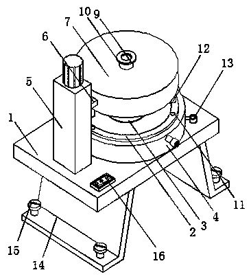
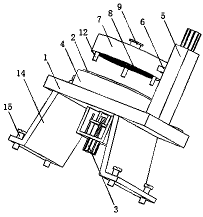
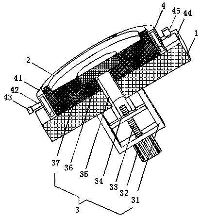
[0024] see Figure 1-5 , the present invention provides the following technical solutions:

[0025]An injection molding mold for advanced ceramic parts, including a base plate 1 for providing support, a lower template 2 is provided on the right side of the upper end of the base plate 1, and an ejection device 3 is provided inside the lower template 2, and the ejection device 3 includes a U-shaped frame 31, The center of the bottom end of the base plate 1 is p...


PUM


Abstract

The invention discloses an advanced ceramic part injection mold and injection molding method. The advanced ceramic part injection mold comprises a base plate. A lower mold plate is arranged at the right side of the upper end of the base plate. An ejection device is arranged inside the lower mold plate. The outer surface of the lower mold plate is provided with a cooling device. A closed separatingdevice is arranged at the left side of the upper end of the base plate. A connecting plate is arranged at the side, close to the center of the lower mold plate, of a support block in the closed separating device. Under the effect of locating pillars and locating holes, an upper mold plate and the lower mold plate are closed through the closed separating device; mixed and compounded slurry is located and guided through a locating annular piece. According to the advanced ceramic part injection mold and injection molding method, the injection mold is simple in structure and convenient to operate; the slurry is injected uniformly and efficiently; the mold can achieve rapid cooling and molding, and materials are convenient and fast to pick; the injection molding method is reasonable and efficient; the injection molding quality of parts is guaranteed; the work load of personnel is lowered; and the injection and molding efficiency is improved.

Description

technical field [0001] The invention relates to the technical field of processing and production of ceramic parts, in particular to an injection molding mold for advanced ceramic parts and an injection molding method thereof. Background technique [0002] Ceramic parts are favored by the market for their unique and excellent characteristics. They often appear in various large-scale equipment parts. In the production process of ceramic parts, special molds are needed for auxiliary support. However, traditional injection molding molds for ceramic parts and There are many problems in its injection molding method, such as complex structure, cumbersome operation, insufficient uniformity and efficiency of slurry injection, injection molding often has a large amount of injection at a single position, the molding quality and molding efficiency are greatly affected, the cooling molding efficiency of the mold is not high, and the material retrieving It is not convenient enough, the in...

Claims


Application Information

Patent Timeline
IPC IPC(8): B28B1/26B28B7/42B28B13/06
CPCB28B1/267B28B7/42B28B13/06
Inventor 朱喜英
Owner 湖南犀鸟陶瓷有限公司
Why Eureka
Try Eureka