Display panel packaging box with cushioning function

A technology of display panel and buffer board, applied in the directions of transportation and packaging, types of packaging items, special packaging items, etc. Stable performance and comprehensive protection

Active Publication Date: 2022-04-05
HUIZHOU CHINA STAR OPTOELECTRONICS TECHNOLOGY CO LTD
View PDF10 Cites 0 Cited by
  • Summary
  • Abstract
  • Description
  • Claims
  • Application Information

AI Technical Summary

Problems solved by technology

However, due to the inevitable precision error in the manufacturing process, there will still be a certain gap after the packaging box is loaded into the display panel, so this packaging box is not suitable for display panels with high resolution and ultra-narrow borders, because the high The resolution and ultra-narrow bezel chip-on-chip are very dense. In the case of a long printed circuit board, if the displacement of the display panel cannot be stably limited, it is easy to cause damage to the liquid crystal glass or the connection of the chip-on-chip during transportation. Tearing causes poor display
[0004] In addition, in the prior art, in order to allow the stopper to closely fit the display panel to alleviate the impact force, the stopper can also be designed as an independent component, and the stopper can be placed in the packing box before loading the display panel, This method has the disadvantage of inconvenient installation of the display panel
Of course, it is also possible to put a stopper after installing the display panel, such as inserting the stopper into the gap between the panel and the packing box, but this method is time-consuming and laborious, and the panel will be accidentally damaged during the operation, and the stopper will be damaged during transportation. The position also changes, making it difficult to provide a protective panel anymore

Method used


Image

  • Display panel packaging box with cushioning function
  • Display panel packaging box with cushioning function
  • Display panel packaging box with cushioning function

Examples


Embodiment Construction

[0040] The specific implementation of the display panel packaging box with cushioning function of the present invention will be given below in conjunction with the accompanying drawings, but it should be pointed out that the specific implementation is not intended to limit the specific implementation of the present invention. All similar structures and similar changes using the present invention should be included in the protection scope of the present invention. The following description of the embodiments refers to the accompanying drawings to illustrate specific embodiments in which the invention may be practiced. The directional terms mentioned in the present invention, such as "up", "down", "front", "back", "left", "right", "top", "bottom", etc., are only for reference to the attached drawings. direction. Therefore, the directional terms used are used to illustrate and understand the present invention, but not to limit the present invention.

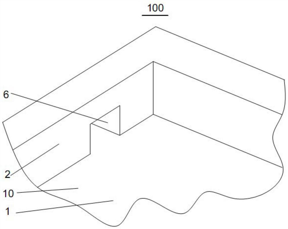
[0041] see figure 1 with ...


PUM


Abstract

The display panel packaging box with cushioning function of the present invention includes a bottom plate and four side walls, the four side walls are vertically connected to the bottom plate, and the bottom plate and the four side walls jointly enclose an accommodating space , the accommodating space is used to place the display panel, and the display panel packaging box with buffer function also includes a buffer device and a locking device; before loading the display panel, the buffer device is compressed by the locking device , the compressed buffer device is placed in the packing box, and will not interfere with the packing of the display panel. After the buffer device is loosened, self-adaptive adjustment can be realized, and the display panel can be closely attached to stabilize the panel. effect.

Description

technical field [0001] The invention relates to the packaging field of display panels, in particular to a display panel packaging box with a buffer function. Background technique [0002] With the progress and development of science and technology, various display terminals are more and more integrated into our lives, and the panel industry has also ushered in a bonus period, and a large number of panels are produced. The liquid crystal display panel is connected to a printed circuit board (Printed Circuit Board, PCB) through a Chip On Flex (or, Chip On Film, COF) to realize signal transmission. [0003] The semi-finished display panels and finished display panels produced on each production line are transferred through packing boxes. During the transfer operation, there will be gaps between the packing boxes and the display panels, and the original packing boxes will be provided with fixed retaining walls or blocks around them. Reduce the amount of active displacement of t...

Claims


Application Information

Patent Timeline
Patent Type & Authority Patents(China)
IPC IPC(8): B65D81/05B65D25/02B65D85/30
CPCB65D25/02B65D81/05B65D85/30
Inventor 李小华崔宽
Owner HUIZHOU CHINA STAR OPTOELECTRONICS TECHNOLOGY CO LTD
Why Eureka
Try Eureka