Self-pressing device for glass pressing machine

A calender and glass technology, applied in glass calendering, glass forming, glass manufacturing equipment, etc., can solve the problems of unstable pressure value, high production cost, occupying workshop space, etc., to improve automation control and reduce production cost , the effect of compact device structure

Pending Publication Date: 2019-04-19
BENGBU TRIUMPH ENG TECH CO LTD
View PDF0 Cites 1 Cited by
  • Summary
  • Abstract
  • Description
  • Claims
  • Application Information

AI Technical Summary

Problems solved by technology

[0002] In the glass calendering production line, the calender is the key equipment for glass forming. When producing thin glass, the pressure between the two calender rollers of the calender is not enough to make the glass thinner, so an additional pressure device is required to force the upper roller down. Pressing to ensure the thickness of the glass ribbon; the pressure device mainly used at present, usually adopts the following method: set up a steel structure platform above the calender, hang two long rods from the platform to the bearing seat of the upper roller of the calender, and pass through the elevator and lever mechanism to drive two long rods to achieve the purpose of pressurization. In actual production, precision electromechanical equipment such as motors, elevators and sensors for pressure detection need to operate in a high temperature environment for a long time. Due to the nature of hot air floating up, It has a serious impact on the life, reliability and accuracy of the equipment. At the same time, the large size of the steel structure platform makes it difficult to control the elastic deformation and vibration, which eventually causes the pressure value to be unstable, affecting the thickness difference and pass rate of the glass. Occupies a lot of workshop space, affects the operation and maintenance of the calender by the staff, and the production cost is high

Method used


Image

  • Self-pressing device for glass pressing machine

Examples


Embodiment Construction

[0021] In order to facilitate those skilled in the art to understand the technical solution of the present invention, the technical solution of the present invention will be further described in conjunction with the accompanying drawings.

[0022] In this application, terms such as "installation", "connection", "connection" and "fixation" should be interpreted in a broad sense, for example, it can be a fixed connection or a detachable connection, unless otherwise clearly specified and limited. , or integrated; it can be a mechanical connection, an electrical connection, or a communication; it can be a direct connection or an indirect connection through an intermediary, it can be the internal communication of two components or the interaction relationship between two components . Those of ordinary skill in the art can understand the specific meanings of the above terms in this application according to specific situations.

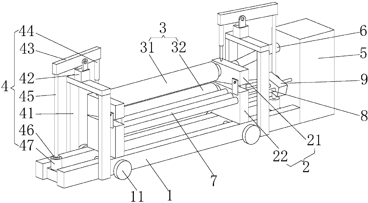
[0023] refer to figure 1 , this embodiment discloses...


PUM


Abstract

The invention discloses a self-pressing device for a glass pressing machine. The device comprises a base, bearing sets, a pressing roller set, a self-pressing device body and a transmission device, the bearing sets are fixed to the base, and the pressing roller set is fixed between the bearing sets; the self-pressing device body is fixed to the two sides, away from the pressing roller sets, of thebearing sets and located on the base, the transmission device is fixed to one end portion of the base and connected with the pressing roller set, and the bearing sets comprise the upper bearing set and the lower bearing set; the pressing roller set comprises an upper pressing roller and a lower pressing roller, and the self-pressing device body comprises a U-shaped truss, a hinge support, a lever, a pressing rod, a connecting rod, a sensor and a lifting device. The self-pressing device is characterized in that the influence of high temperature on the service life, reliability and accuracy ofthe sensor and the lifting device is reduced, the structure is compact, the production cost is reduced, and stable pressure between the upper pressing roller and the lower pressing roller is ensured,so that the thickness of glass is uniform, the qualification rate is increased, and automation control is improved.

Description

technical field [0001] The invention relates to the field of rolling glass production equipment, in particular to a self-pressing device for a glass rolling machine. Background technique [0002] In the glass calendering production line, the calender is the key equipment for glass forming. When producing thin glass, the pressure between the two calender rollers of the calender is not enough to make the glass thinner, so an additional pressure device is required to force the upper roller down. Pressing to ensure the thickness of the glass ribbon; the pressure device mainly used at present, usually adopts the following method: set up a steel structure platform above the calender, hang two long rods from the platform to the bearing seat of the upper roller of the calender, and pass through the elevator and lever mechanism to drive two long rods to achieve the purpose of pressurization. In actual production, precision electromechanical equipment such as motors, elevators and sen...

Claims


Application Information

Patent Timeline
Patent Type & Authority Applications(China)
IPC IPC(8): C03B13/18C03B13/01
CPCC03B13/01C03B13/18
Inventor 夏鹏华叶坤彭丹进梁超帝张奎何思源郭哲王松卢佩庆王安乐
Owner BENGBU TRIUMPH ENG TECH CO LTD
Why Eureka
Try Eureka