Fabricated compound wall

A prefabricated, wall technology, applied in the direction of walls, building components, thermal insulation, etc., can solve the problems of poor living comfort, large displacement between buildings, low rigidity of light steel structures, etc., to save project cost, save labor, avoid The effect of transport

Pending Publication Date: 2019-04-19
HEZHOU UNIV +1
View PDF0 Cites 6 Cited by
  • Summary
  • Abstract
  • Description
  • Claims
  • Application Information

AI Technical Summary

Problems solved by technology

[0004] The purpose of the present invention is to propose a prefabricated composite wall to solve the lack of transportation and construction conditions in the prefabricated concrete structure in the prior art, the high cost and the low rigidity of the light steel structure, resulting in large displacement between building floors. The living comfort is poor, and the steel structure also has problems such as poor fire resistance and poor corrosion resistance

Method used


Image

  • Fabricated compound wall
  • Fabricated compound wall
  • Fabricated compound wall

Examples


Embodiment Construction

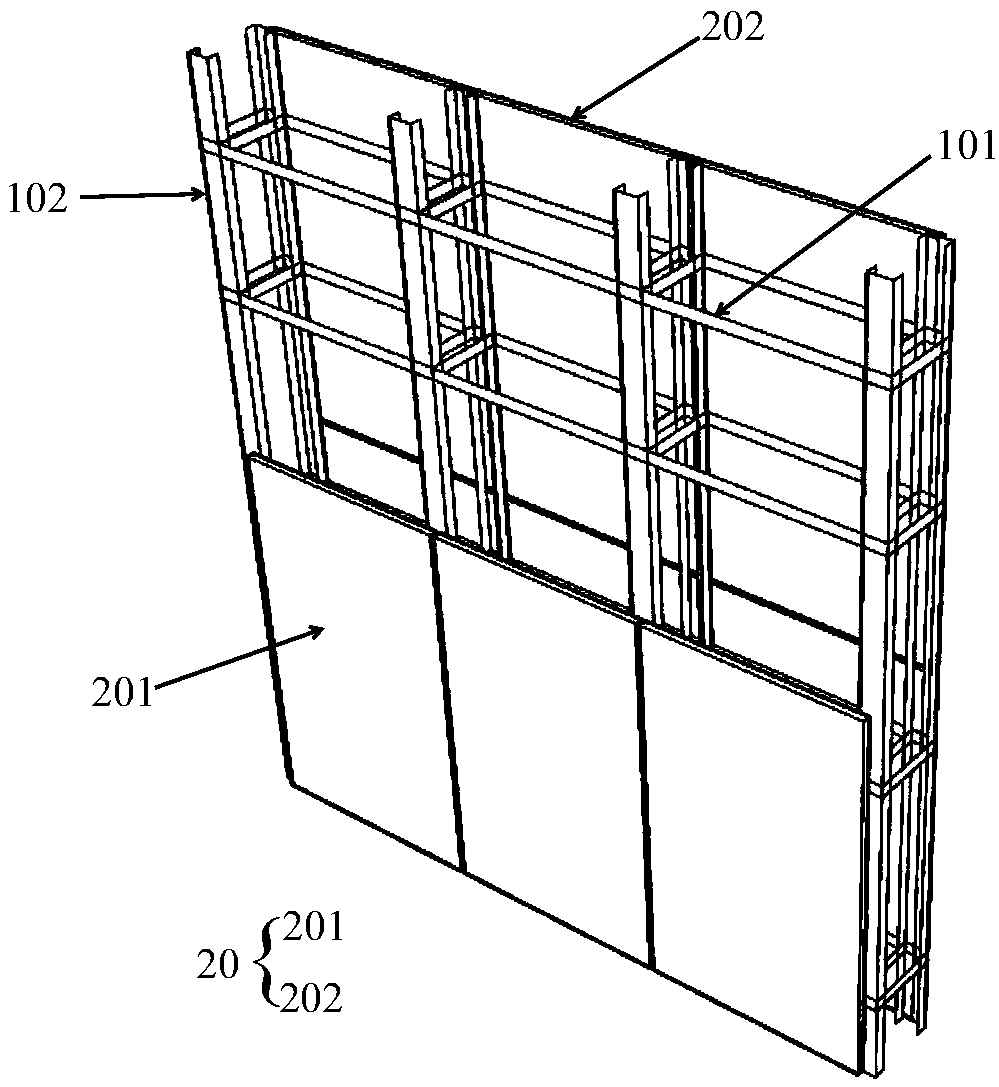
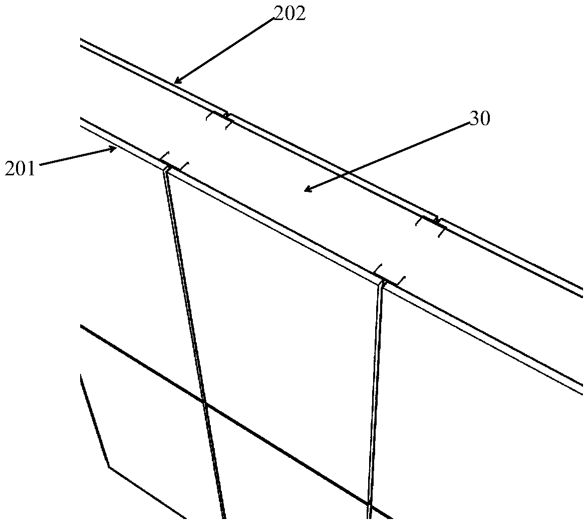
[0021] A prefabricated composite wall proposed by the present invention will be described in further detail below in conjunction with the accompanying drawings and specific embodiments. Advantages and features of the present invention will be apparent from the following description and claims. It should be noted that all the drawings are in a very simplified form and use imprecise scales, and are only used to facilitate and clearly assist the purpose of illustrating the embodiments of the present invention.

[0022] In the description of the present invention, it should be understood that the orientation or positional relationship indicated by the terms "center", "upper", "lower", "left", "right" etc. is based on the orientation or positional relationship shown in the drawings , is only for the convenience of describing the present invention and simplifying the description, but does not indicate or imply that the referred device or element must have a specific orientation, be ...


PUM


Abstract

The invention provides a fabricated compound wall. The fabricated compound wall has a light steel structure as the skeleton, and the inner side and the outer side of the fabricated compound wall are nailed with fabricated slabs and can be poured with light insulating cement-based materials. Therefore, the fabricated compound wall is light in construction and installation as the steel structure andmeanwhile solves the problems of poor fireproof and antiseptic performance and small structural rigidity of steel structures; besides, plant fabrication of the prefabricated slabs can save field manual labors, the prefabricated slabs serving as a mouldless and support-free system can accelerate field pouring of the light insulating cement-based materials, avoid transportation of large fabricatedconcrete components, save engineering costs and meet the economic conditions in rural areas.

Description

technical field [0001] The invention belongs to the field of construction, in particular to an assembled composite wall. Background technique [0002] Existing concrete prefabricated components are large in size and heavy in weight. When used in rural low-rise and multi-storey buildings, there are problems such as lack of transportation and construction conditions, and high cost. Although the thin-walled light steel structure is light in weight and quick in construction, due to the use of OSB boards and other boards as the structural cladding layer, although the interior of the wall is filled with EPS (polystyrene foam), XPS (extruded polystyrene) or Thermal insulation and sound insulation materials such as rock wool, but the interior of the wall is still a cavity structure, and the wall will make a hollow sound when knocked on the wall, and heavy objects cannot be nailed. In addition, the rigidity of the light steel structure is small, resulting in a large displacement bet...

Claims


Application Information

Patent Timeline
Patent Type & Authority Applications(China)
IPC IPC(8): E04B2/56E04B2/58E04B1/76
CPCE04B2/56E04B1/7604E04B2/562E04B2/58
Inventor 陈宜虎张敏卢旦
Owner HEZHOU UNIV
Why Eureka
Try Eureka