A lead core corrugated steel tube restraining rubber bearing

A corrugated steel pipe and rubber bearing technology, which is applied in building types, buildings, building components, etc., can solve the problems of limited restraint effect of lead cores and inability to exert energy dissipation capacity stably, so as to improve seismic energy dissipation capacity and ensure horizontal isolation. Seismic and reset characteristics, guaranteeing the effect of restraint

Active Publication Date: 2020-12-15
CHINA UNIV OF MINING & TECH
View PDF6 Cites 0 Cited by
  • Summary
  • Abstract
  • Description
  • Claims
  • Application Information

AI Technical Summary

Problems solved by technology

However, due to the direct contact between the rubber and the external environment, durability problems are prone to occur, and the surrounding rubber has limited restraint on the lead core in the center, so that the energy dissipation capacity cannot be stably exerted.

Method used


Image

  • A lead core corrugated steel tube restraining rubber bearing
  • A lead core corrugated steel tube restraining rubber bearing
  • A lead core corrugated steel tube restraining rubber bearing

Examples


Embodiment 1

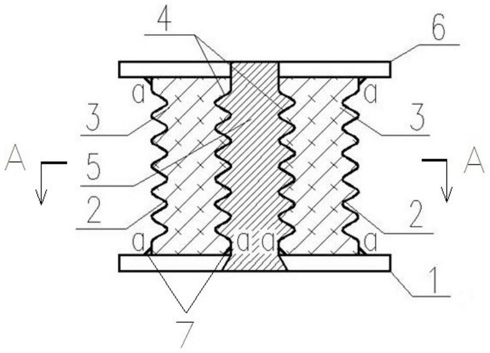
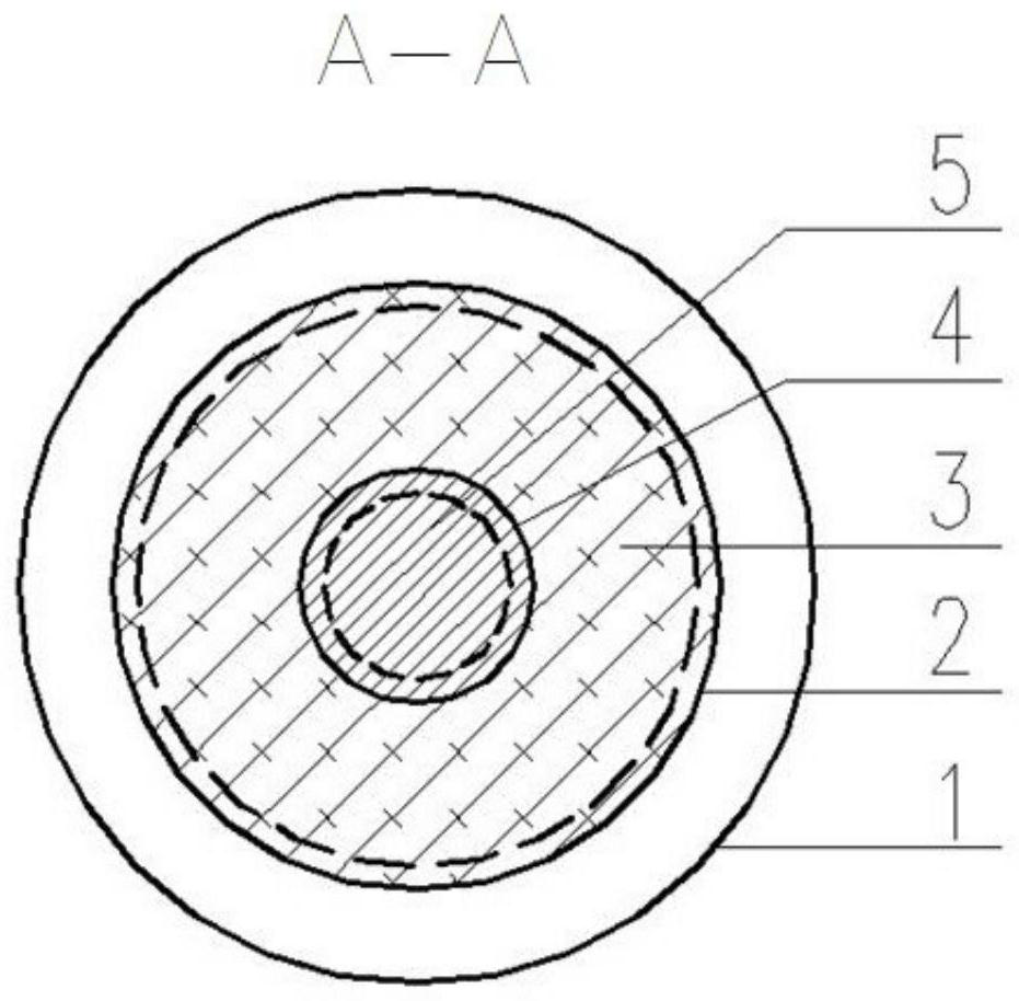
[0018] combine figure 1 and image 3 This embodiment will be specifically described. A lead-core corrugated steel pipe constrained rubber support in this embodiment is arranged between the foundation of the house, the bottom or the substructure and the upper structure, including the lower connecting steel plate 1, the outer corrugated steel pipe 2, the rubber interlayer 3, and the inner corrugated Steel pipe 4, lead core 5 and upper connecting steel plate 6. The lower connecting steel plate 1 is used to connect the support of the present invention with the structural foundation, the bottom or the lower structure. The inner corrugated steel pipe 4 is coaxially installed in the outer corrugated steel pipe 2, and the upper end of the inner corrugated steel pipe 4 is cylindrical and inserted Set in the central hole of the upper connecting steel plate 6, the lower end of the inner layer corrugated steel pipe 4 and the upper and lower ends of the outer layer corrugated steel pipe ...

Embodiment 2

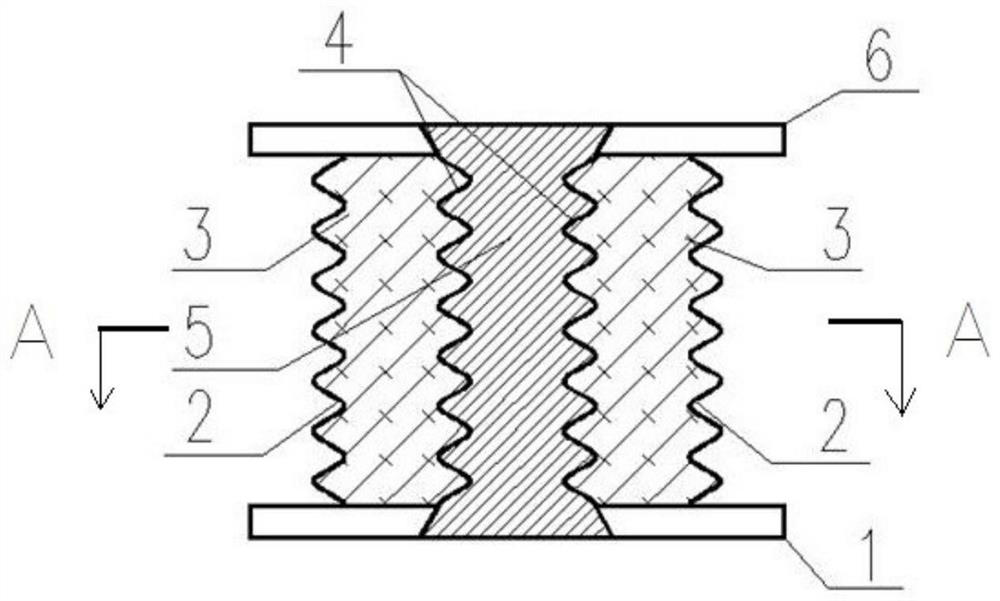
[0023] combine figure 2 and image 3 The difference between this embodiment and Embodiment 1 is that the upper and lower ends of the inner corrugated steel pipe 4 and the upper and lower ends of the outer corrugated steel pipe 2 are respectively positioned with the inner surfaces of the lower connecting steel plate 1 and the upper connecting steel plate 6 by spot welding. .

[0024] The difference in the manufacturing process is: after the outer layer corrugated steel pipe 2 and the inner layer corrugated steel pipe 4 are coaxially positioned at the center of the lower connecting steel plate 1, both are positioned by spot welding with the lower connecting steel plate 1, and then the inner layer corrugated The steel pipe 4 is filled with a lead core 5, and then rubber is added between the outer corrugated steel pipe 2 and the inner corrugated steel pipe 4, and then both the outer corrugated steel pipe 2 and the inner corrugated steel pipe 4 are spot welded to the upper connec...


PUM


Abstract

The invention relates to a lead core corrugated steel pipe restraint rubber supporting seat. The lead core corrugated steel pipe restraint rubber supporting seat comprises a lower connecting steel plate, an upper connecting steel plate and a lead core which is arranged at the centers of the lower and upper connecting steel plates in a penetrating manner, wherein an inner laye corrugated steel pipeand an outer layer corrugated steel pipe are also coaxially arranged between the lower connecting steel plate and the upper connecting steel plate, the lead core is also arranged in a cavity of the inner layer corrugated steel pipe, and a rubber interlayer is also arranged between the outer layer corrugated steel pipe and the inner layer corrugated steel pipe in a filling manner. The lead core corrugated steel pipe restraint rubber supporting seat can also provide annular restraint and protection for the rubber, thereby improving the durability; the restraint effect of the steel pipe and rubber for the lead core can ensure the stability of energy consumption capability of the lead core; and the lead core corrugated steel pipe restraint rubber supporting seat is simple in overall structure, convenient in construction, and good in vertical load bearing characteristics, horizontal transformation capability and anti-seismic energy consumption capability.

Description

technical field [0001] The invention relates to a shock-isolation support used in construction engineering, in particular to a lead-core corrugated steel pipe-constrained rubber support which can be used in the shock-isolation design of buildings in anti-seismic fortification areas, and belongs to the technical field of construction engineering. Background technique [0002] my country is a country with frequent earthquakes, and the most widely used structural anti-seismic means at this stage is to resist the predicted earthquake action through the anti-seismic performance of the structure itself. However, under the action of a strong earthquake, irreparable damage may occur to the structure, causing significant economic losses or casualties. The seismic isolation system absorbs and dissipates seismic capacity by setting a seismic isolation system between the foundation and the superstructure, reducing the seismic action input into the superstructure, and can effectively res...

Claims


Application Information

Patent Timeline
Patent Type & Authority Patents(China)
IPC IPC(8): E04B1/98E04H9/02E04B1/36
CPCE04B1/36E04H9/021
Inventor 李贤周涛赵雨薇孙晓栋李世博苑东瑞苏蓉马梦婷
Owner CHINA UNIV OF MINING & TECH
Why Eureka
Try Eureka