Eureka AIR delivers breakthrough ideas for toughest innovation challenges, trusted by R&D personnel around the world.

Gas pressurizer

A gas pressurizer and main body technology, which is applied in the direction of machines/engines, liquid variable displacement machinery, pump testing, etc., can solve the problems of slow pressurization, swelling of sealing rubber rings, difficulty in replacing rubber rings, etc., to achieve extended use The effect of life and force uniformity

Inactive Publication Date: 2019-04-19
CHINA UNIV OF PETROLEUM (EAST CHINA)
View PDF5 Cites 2 Cited by
  • Summary
  • Abstract
  • Description
  • Claims
  • Application Information

AI Technical Summary

Problems solved by technology

However, these two pressurization methods are often very slow, and for some experiments that require the time for the gas to reach the specified pressure, it affects the accuracy of the experimental results; and when pressurizing corrosive gases, such as carbon dioxide gas, It is easy to swell the sealing rubber ring, and it is difficult to replace the rubber ring of the gas booster pump

Method used


Image

  • Gas pressurizer
  • Gas pressurizer

Examples


Embodiment 1

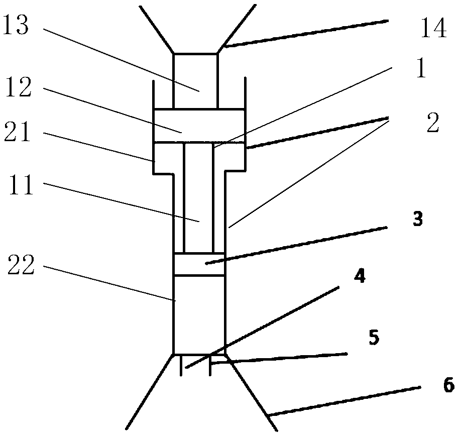
[0034] Embodiment 1 of the present invention provides a gas pressurizer, refer to figure 1 As shown, it includes: a cylinder 1, a main body 2 and a piston 3; the main body 2 is a main body with a stepped hole inside, wherein the end 21 with a larger hole is threaded (not shown in the figure); the bottom of the main body 2 is sealed and At least two gas inlets and outlets 4 and 5 are provided, and the top of the main body 2 is open; the cylinder 1 includes a piston rod 11 connected with the piston 3 and a threaded rod 12 connected with the piston rod 11, and the cross-sectional area of ​​the threaded rod 12 is larger than that of the piston. The cross-sectional area of ​​the rod 11; the threaded rod 12 is threadedly connected to the end 21 with the larger aperture of the main body 2; the piston 3 matches the end 22 with the smaller aperture of the main body 2; Groove (not shown in the figure), air-tight connection by rubber ring.

[0035] The traditional gas pressurization met...

Embodiment 2

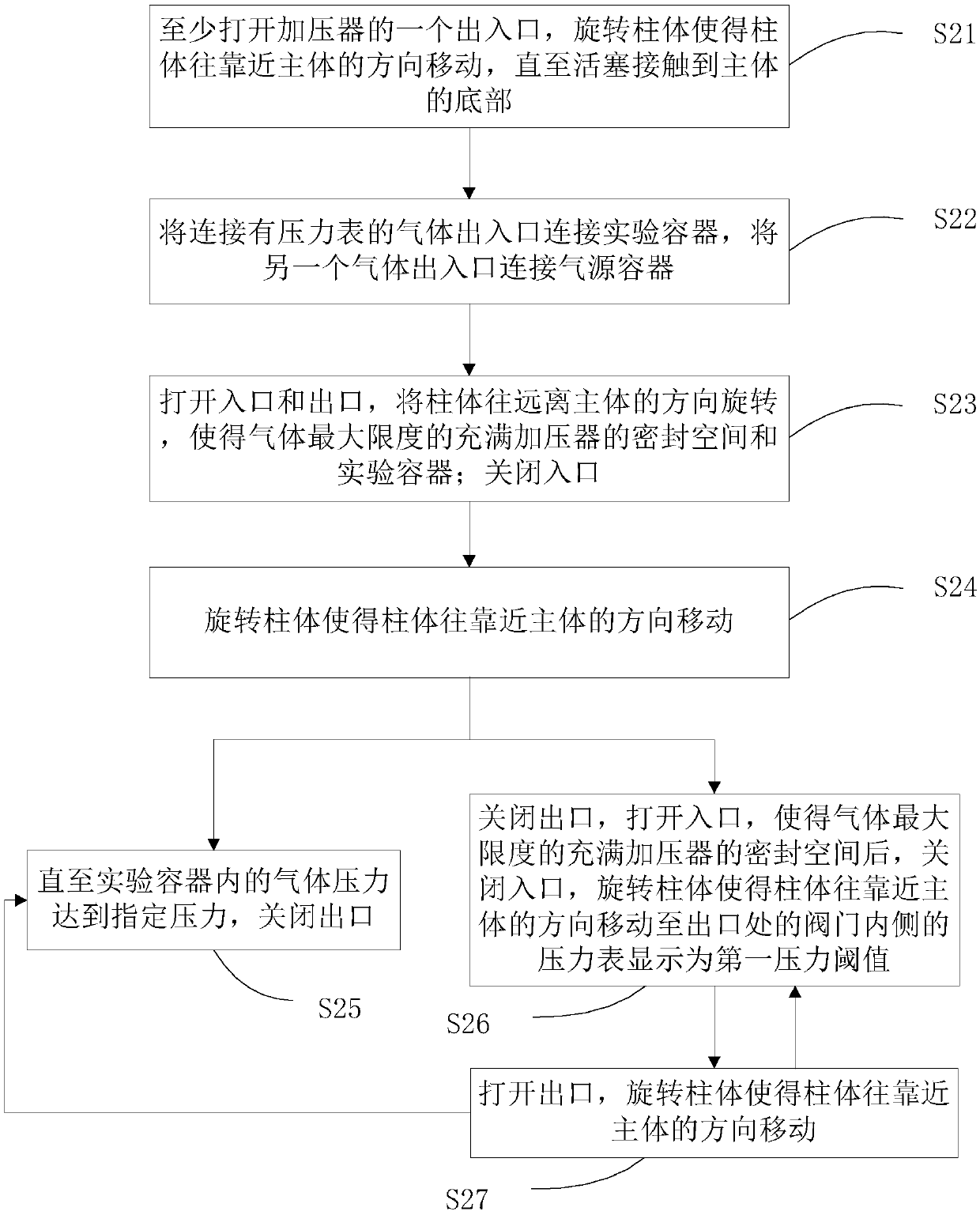
[0057] Embodiment 2 of the present invention provides a method for using the gas pressurizer described in Embodiment 1. Refer to figure 2 shown, including the following steps:

[0058] Step S21: Open at least one inlet and outlet of the pressurizer, and rotate the cylinder so that the cylinder moves toward the main body until the piston touches the bottom of the main body.

[0059] When the piston touches the bottom of the main body, all the gas in the main body can be evacuated, so as to avoid the influence of other gases on the experimental results.

[0060] Step S22: Connect the gas inlet and outlet connected with the pressure gauge to the experimental container, and connect the other gas inlet and outlet to the gas source container.

[0061] The above-mentioned gas source container, that is, the container containing the gas required for the experiment, provides the gas source for the experimental container; the gas injected into the experimental container needs to be pre...


PUM

PropertyMeasurementUnit
Depthaaaaaaaaaa
Pitchaaaaaaaaaa

Abstract

The invention discloses a gas pressurizer, comprising a cylinder body, a main body and a piston; a stepped hole is formed in the main body, wherein one end with a larger hole diameter is provided withthreads; the bottom of the main body is sealed and provided with at least two gas inlets and outlets and the top of the main body is open; the cylinder body comprises a piston rod connected with thepiston and a threaded rod connected with the piston rod; the cross-sectional area of the threaded rod is larger than that of the piston rod; the threaded rod is in threaded connection with one end ofthe main body with a larger hole diameter; the piston is matched with one end of the main body with smaller hole diameter; the side wall of the piston is provided with at least one groove in which a rubber ring is placed, and airtight connection is realized through the rubber ring. The gas pressurizer provided by the invention can pressurize gas rapidly, and the rubber ring is convenient to replace.

Description

technical field [0001] The invention relates to the technical field of experimental equipment, in particular to a gas pressurizer. Background technique [0002] When doing experiments in the laboratory, it is often necessary to pressurize the gas to make it meet certain pressure conditions. At present, the gas is mainly pressurized by a gas pressurizing pump, or by a syringe pump and an intermediate container. However, these two pressurization methods are often very slow. For some experiments that require the time required for the gas to reach the specified pressure, the accuracy of the experimental results will be affected; and when pressurizing corrosive gases, such as carbon dioxide gas, It is easy to swell the sealing rubber ring, and it is difficult to replace the rubber ring of the gas pressure pump. SUMMARY OF THE INVENTION [0003] In view of the above-mentioned problems, the present invention has been proposed in order to provide a gas pressurizer that overcomes...

Claims


Application Information

Patent Timeline
IPC IPC(8): F04B39/00F04B39/10F04B51/00
CPCF04B39/00F04B39/0005F04B39/0022F04B39/1046F04B51/00
Inventor 苏玉亮李东升李蕾王文东郝永卯
Owner CHINA UNIV OF PETROLEUM (EAST CHINA)
Why Eureka
Eureka Blog
Learn More