Energy-saving type water collecting device
A water collector and energy-saving technology, applied in the direction of branch pipelines, pipes, pipes/pipe joints/fittings, etc., can solve the problems of increasing pump power waste, consuming water flow energy, increasing operating costs, etc., to reduce turbulent flow Impact, reduce noise, smooth water effect
- Summary
- Abstract
- Description
- Claims
- Application Information
AI Technical Summary
Problems solved by technology
Method used
Image
Examples
Embodiment 1
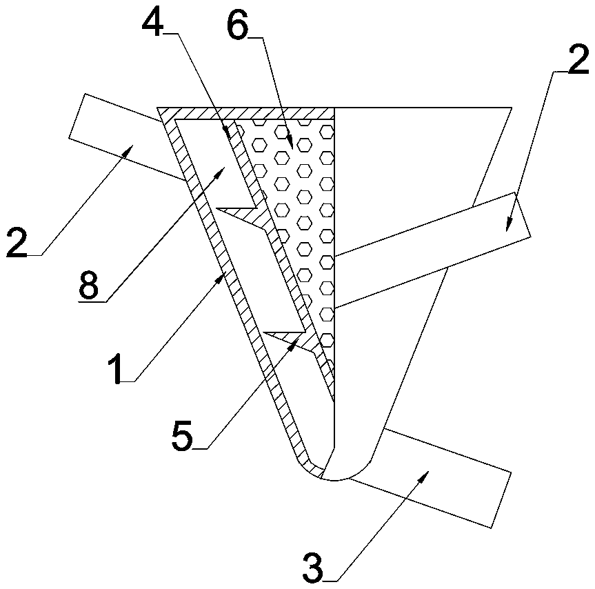
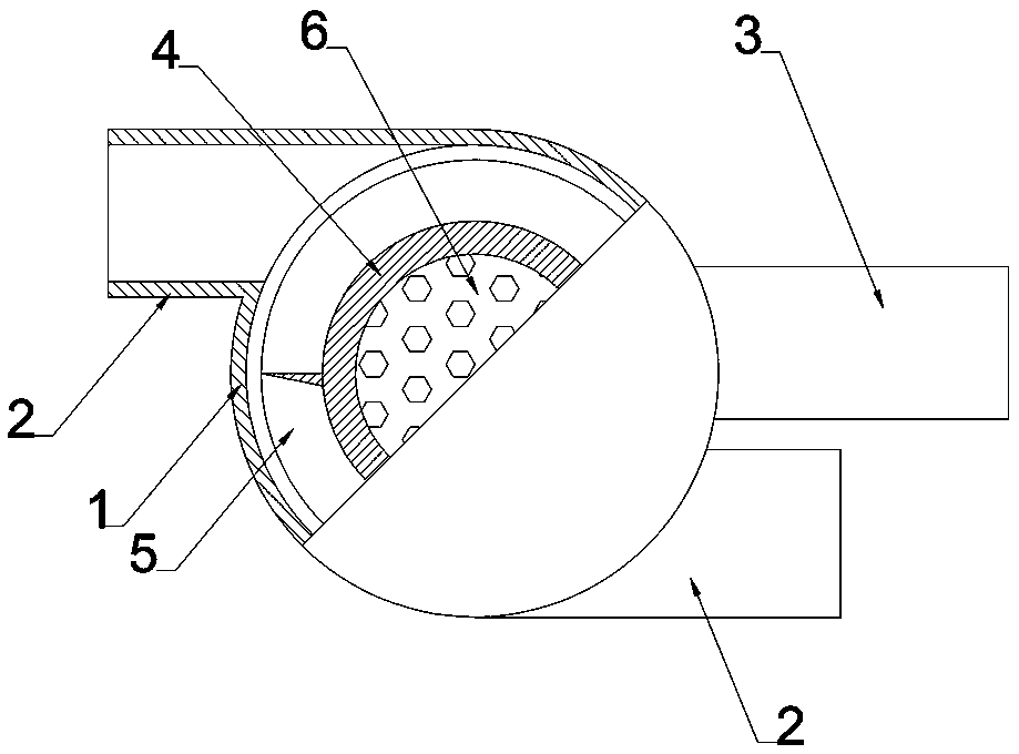
[0028] Such as Figure 1 to Figure 4 As shown, this embodiment is an energy-saving water collector, which includes a housing 1 , a water outlet pipe 3 and at least one water inlet pipe 2 .
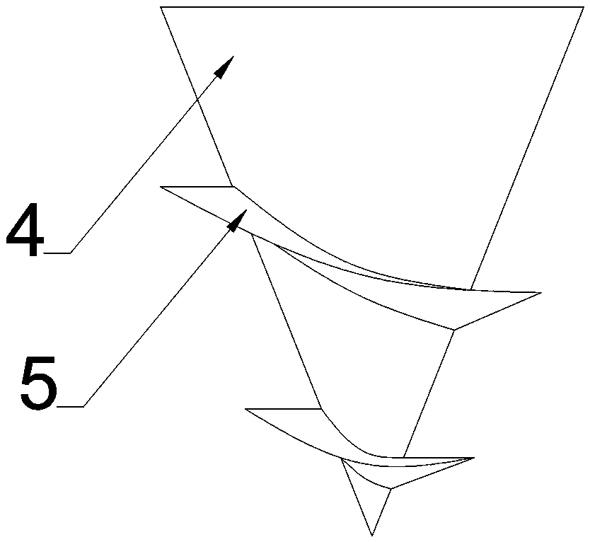
[0029] The shell is conical, and a conical flow guide core 4 is set inside the shell 1; the surface of the shell 1 is parallel to the flow guide core 4, with a gap 8 therebetween; the flow guide core 4 The ends are connected to the shell 1 by welding or bolts.
[0030] The outer surface of the flow guide core 4 is provided with a flow guide device 5; the flow guide device 5 is a continuous spiral protrusion. The cross-section of the spiral protrusion is a right-angled triangle or an obtuse-angled triangle, and one side of the right-angled or obtuse-angled side faces the water inlet direction. This arrangement limits the lateral direction of the water flow (also in the axial direction of the water collector), so that the influent water flow can be kept as independent as possible and not i...
Embodiment 2
[0043] This embodiment is also an energy-saving water collector. Compared with Embodiment 1, its basic structure is similar, and the main difference is that the number of water inlet pipes 2 is 3, and the height of the flow guide device 5 is equal to 1 / 2 of the height of the gap 8 , the distance between the adjacent 2-layer spirals of the flow guide device 5 is the same as the gap; the angle between the water inlet pipe and the axial direction of the water collector is 90°; the diameter of the water inlet pipe is 1 / 2 of the height of the gap 8; The diameter of the water pipe is equal to the height of the gap 8; the apex angle of the cone between the shell and the flow guide core 4 is 60°.
[0044] During the verification process, it was found that if the height of the helical protrusion of the diversion device 5 is lower than 1 / 2 of the height of the gap 8, it is difficult to guarantee the lateral restriction of the flow direction of the water flow, so it is better not to be lo...
Embodiment 3
[0050] This embodiment is also an energy-saving water collector. Compared with Embodiment 1, its basic structure is similar, and the main difference is that: the number of water inlet pipes 2 is 4; 3 / 5; the distance between the adjacent 2-layer spirals of the flow guiding device 5 is 1.5 times the height of the gap 8; the angle between the water inlet pipe and the axial direction of the water flow in the water collector is 110°; the shell The cone angle with the guide core (4) is 90°.
[0051] The diameter of the water inlet pipe is 7 / 12 of the height of the gap (8); the diameter of the outlet pipe is 1.5 times of the height of the gap (8). According to the circle area formula πr 2 , we can calculate that in this embodiment, the diameter of the water outlet pipe 3 should be greater than or equal to the diameter of the water inlet pipe 2, that is, 7 / 12 of the height of the gap 8. The setting of this embodiment will not cause insufficient drainage.
PUM
 Abstract
Description
Claims
Application Information
 - R&D
- Intellectual Property
- Life Sciences
- Materials
- Tech Scout
- Unparalleled Data Quality
- Higher Quality Content
- 60% Fewer Hallucinations
Browse by: Latest US Patents, China's latest patents, Technical Efficacy Thesaurus, Application Domain, Technology Topic, Popular Technical Reports.
© 2025 PatSnap. All rights reserved.Legal|Privacy policy|Modern Slavery Act Transparency Statement|Sitemap|About US| Contact US: help@patsnap.com


