Leg structure of mobile speedometer
A speedometer, mobile technology, applied in the direction of supporting machines, machine platforms/supports, mechanical equipment, etc., can solve the problems of inconvenient retracting and inconvenient speed measurement on different road sections, so as to reduce the occupied space, ensure stability, Ease of movement
- Summary
- Abstract
- Description
- Claims
- Application Information
AI Technical Summary
Problems solved by technology
Method used
Image
Examples
Embodiment 1
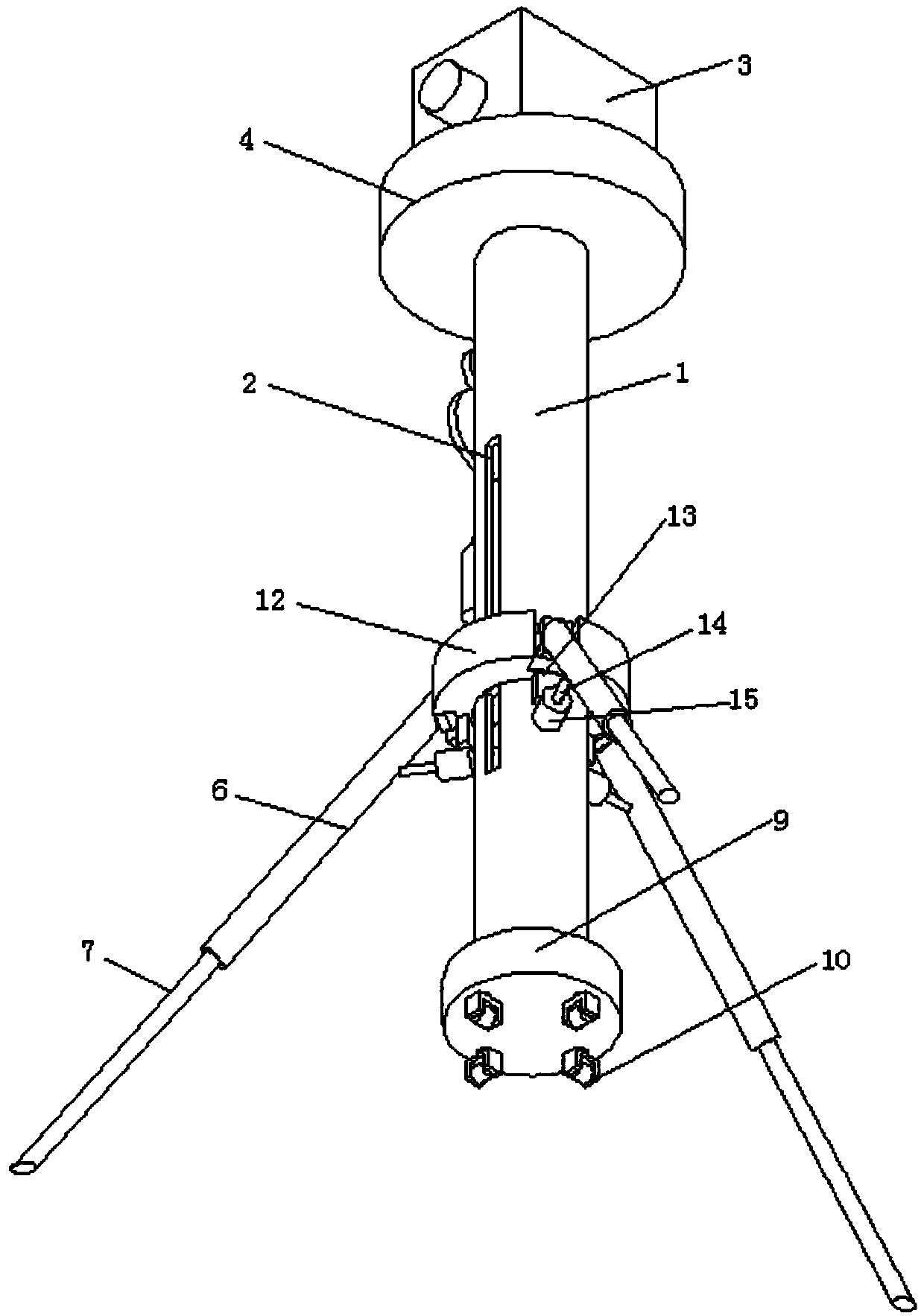
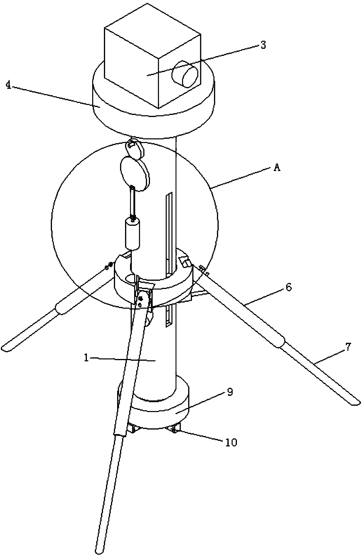
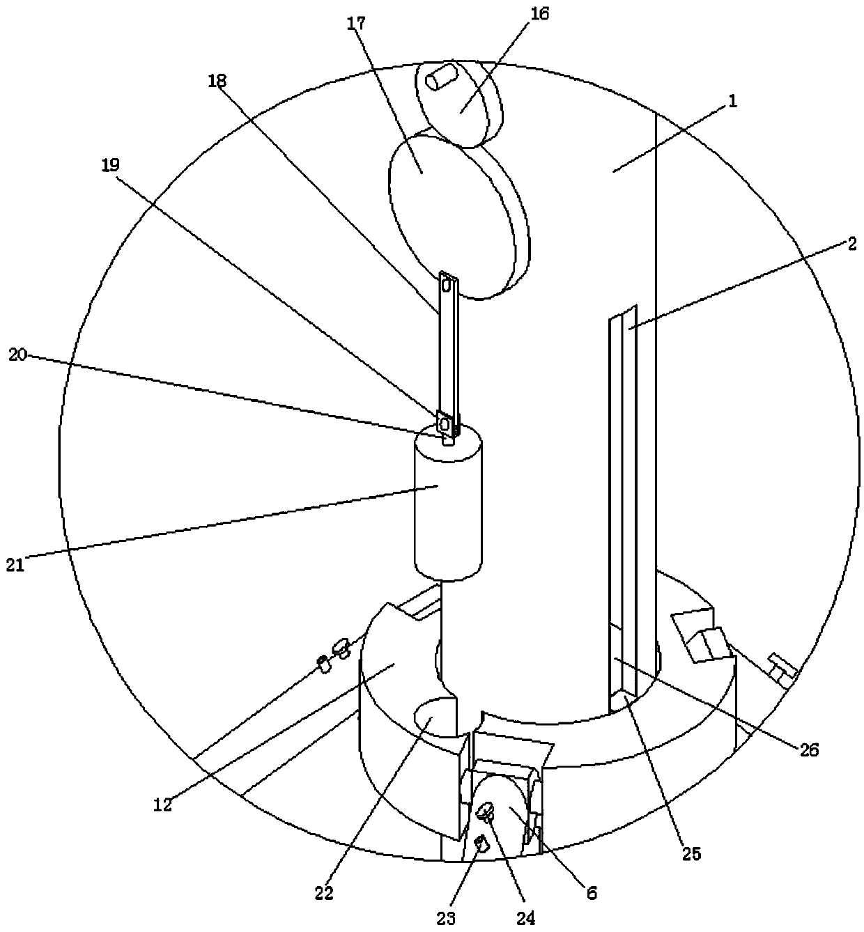
[0031] refer to Figure 1-9 , a mobile speedometer, comprising a radar speedometer 3 and a support cylinder 1, the support cylinder 1 supports the radar speedometer 3 through a support plate 4, a base 9 is provided for sliding on the bottom side of the support cylinder 1, and a universal joint is connected to the bottom side of the base 9 The wheel 10 and the base 9 are slidably connected to the bottom side of the support cylinder 1 through the insertion rod 8. The support cylinder 1 is slidably connected with a sliding sleeve 12, and the sliding sleeve 12 is connected with a support leg 6; when the speedometer needs to be moved, the sliding sleeve 12 Moving upwards drives the supporting legs 6 to move upwards, leaving the ground, and pulling out the insertion rod 8 on the bottom side of the supporting cylinder 1 downwards, so that the base 9 moves downwards, and the universal wheels 10 touch the ground, so that it is easy to move and realize different road sections. For detec...
Embodiment 2
[0034] refer to Figure 1-9, a mobile speedometer, comprising a radar speedometer 3 and a support cylinder 1, the support cylinder 1 supports the radar speedometer 3 through a support plate 4, a base 9 is provided for sliding on the bottom side of the support cylinder 1, and a universal joint is connected to the bottom side of the base 9 The wheel 10 and the base 9 are slidably connected to the bottom side of the support cylinder 1 through the insertion rod 8. The support cylinder 1 is slidably connected with a sliding sleeve 12, and the sliding sleeve 12 is connected with a support leg 6; when the speedometer needs to be moved, the sliding sleeve 12 Moving upwards drives the supporting legs 6 to move upwards, leaving the ground, and pulling out the insertion rod 8 on the bottom side of the supporting cylinder 1 downwards, so that the base 9 moves downwards, and the universal wheels 10 touch the ground, so that it is easy to move and realize different road sections. For detect...
Embodiment 3
[0039] refer to Figure 1-9 , a mobile velocimeter, basically the same as Embodiment 2, furthermore, the lifting plate 26 is fixedly connected to the sliding sleeve 12 through the connecting block 25, and the supporting cylinder 1 is provided with a sliding port 2 matching the connecting block 25, The lifting plate 26 and the sliding sleeve 12 can be connected stably through the connecting block 25, and the sliding opening 2 provided by the support tube 1 ensures that the lifting plate 26 and the sliding sleeve 12 can slide up and down while being fixedly connected on the support tube 1;
[0040] A piston 41 is slidably connected in the pneumatic cylinder 15, and the piston 41 is fixedly connected with the pneumatic rod 14, and the air release valve 40 is connected to the pneumatic cylinder 15; by inflating the pneumatic cylinder 15, the piston 41 is pushed to move, thereby realizing the The movement of the pneumatic rod 14 facilitates the expansion of the supporting legs 6; ...
PUM
 Abstract
Description
Claims
Application Information
 - R&D
- Intellectual Property
- Life Sciences
- Materials
- Tech Scout
- Unparalleled Data Quality
- Higher Quality Content
- 60% Fewer Hallucinations
Browse by: Latest US Patents, China's latest patents, Technical Efficacy Thesaurus, Application Domain, Technology Topic, Popular Technical Reports.
© 2025 PatSnap. All rights reserved.Legal|Privacy policy|Modern Slavery Act Transparency Statement|Sitemap|About US| Contact US: help@patsnap.com


