High-efficiency cooling structure for high-speed conductive slip ring
What is Al technical title?
Al technical title is built by PatSnap Al team. It summarizes the technical point description of the patent document.
A conductive slip ring and cooling structure technology, which is applied in cooling/ventilation/heating transformation, modification with gaseous coolant, circuit, etc., can solve the problem of low heat exchange efficiency between the cooling medium and the temperature rise point, and achieve simple installation, Simple and compact structure and improved cooling efficiency
Inactive Publication Date: 2019-04-19
CHINA PRECISION ENG INST FOR AIRCRAFT IND AVIC
View PDF2 Cites 5 Cited by
Summary
Abstract
Description
Claims
Application Information
AI Technical Summary
This helps you quickly interpret patents by identifying the three key elements:
Problems solved by technology
Method used
Benefits of technology
Problems solved by technology
This structure avoids the problem of low heat exchange efficiency between the cooling medium and the temperature rise point when the slip ring insulation sheet is too high or the friction point is deep, so that the cooling efficiency is greatly improved
Method used
Image
Click on the blue label to locate the original text in one second.
Reading with bidirectional positioning of images and text.
Examples
Embodiment Construction
[0018] Embodiments of the present invention will be further described in detail below in conjunction with the accompanying drawings and examples. The detailed description and drawings of the following embodiments are used to illustrate the principle of the present invention, but not to limit the scope of the present invention, that is, the present invention is not limited to the described embodiments.
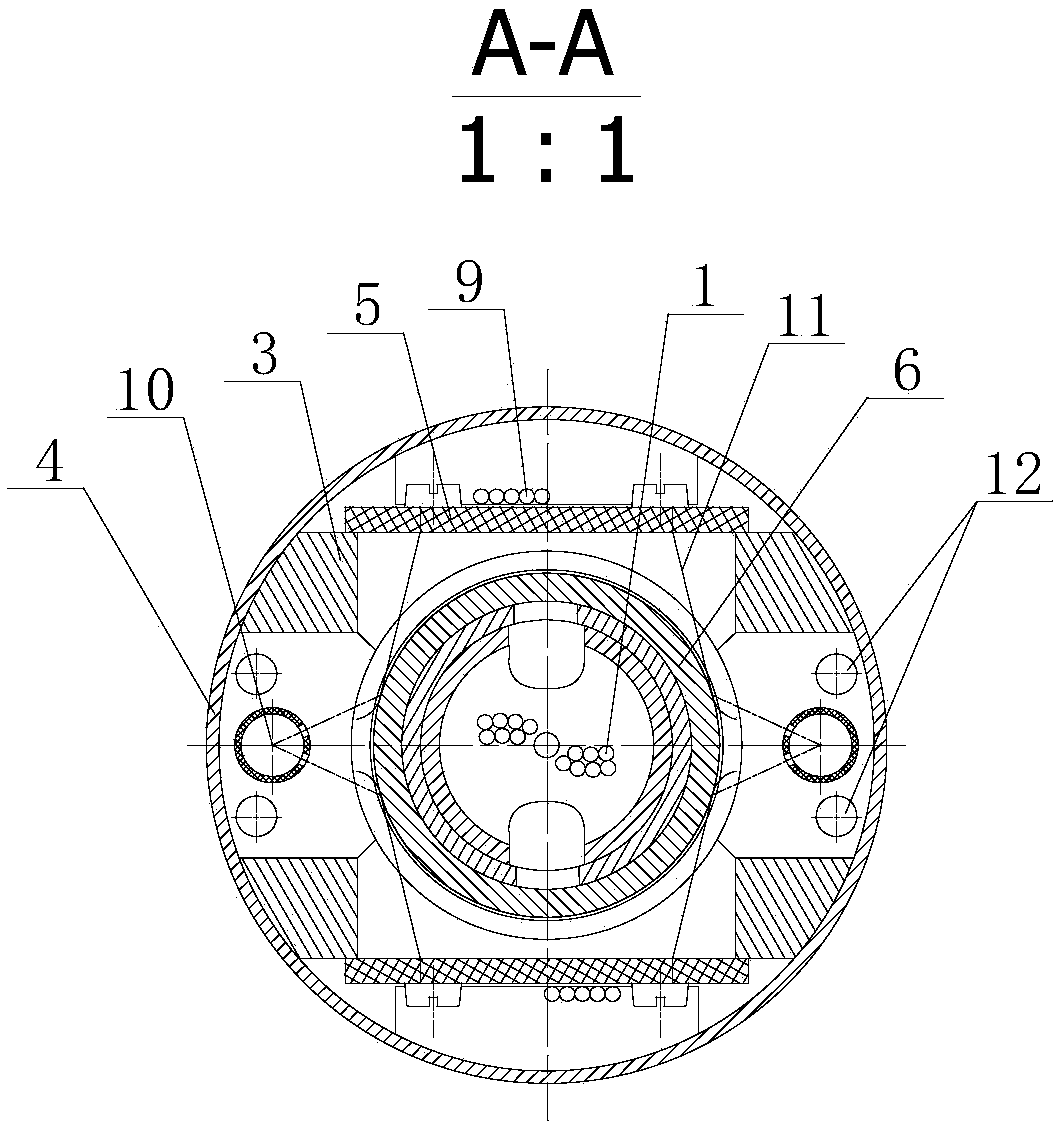
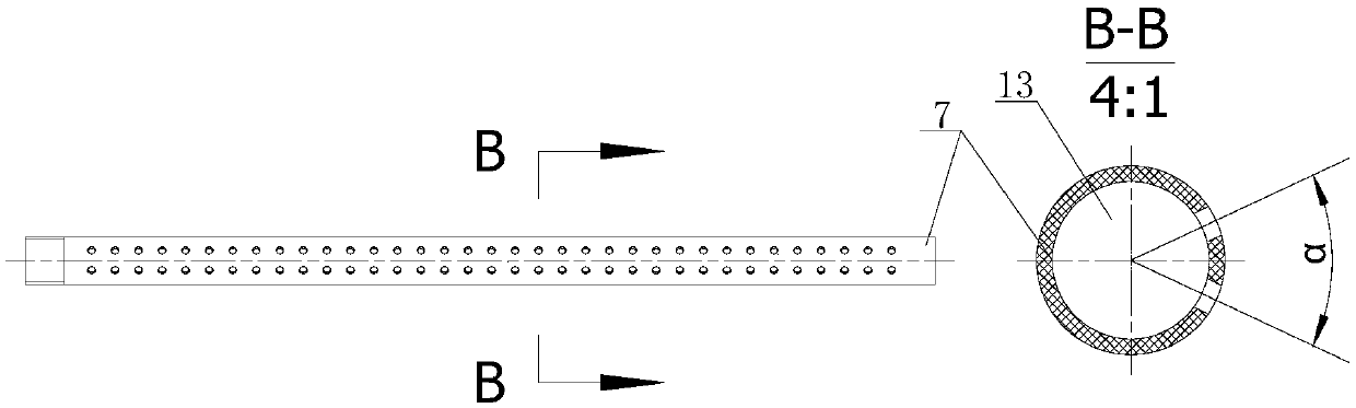
[0019] This embodiment shows a high-speed conductive slip ring high-efficiency cooling structure, including ring outlet 1, shift fork 2, bracket 3, outer cover 4, brush holder plate 5, ring piece, mandrel 6, air pipe 7, air inlet air pipe joint 8. Brush outlet 9, air inlet 10, brush wire 11, air outlet 12, plug 13, dynamic sealing ring 14.
[0020] Such as figure 1 figure 2 As shown, the mandrel 6, the ring piece, the shift fork 2 and the ring outlet 1 form the rotor part; the brush wire 11, the brush holder plate 5, the bracket 3 and the outer cover 4 form the stator part. ...
PUM
Abstract
The invention discloses a high-efficiency cooling structure for a high-speed conductive slip ring. The structure comprises a ring outgoing line, a shifting fork, a bracket, an outer cover, a brush carrier plate, a ring piece, a core shaft, an air pipe, an air inlet hole, an air pipe joint, a brush outgoing line, an air inlet hole, a brush wire, an air outlet hole, a plug and a movable sealing ring. The core shaft, the ring piece fixed on the core shaft, the shifting fork and the ring outgoing line form a rotor part; the brush wire is fixed on the brush carrier plate, the brush carrier plate isfixed on the bracket through a bolt, and the outer cover and the bracket are assembled to form a stator part; the air inlet hole and the air outlet hole are formed in the same end of the bracket, andone ends of the two air pipes are connected with the symmetrical air inlet holes in the sliding ring, and the other ends are plugged by plugs and extend into the sliding ring; and outside the slip ring, the air pipe joint is connected with the air inlet, and the rotor part and the stator part rotate relatively through a bearing. The structure can greatly improve the cooling efficiency, and solvesthe problem that the heat exchange efficiency of a cooling medium and a temperature rise point is low when a slip ring insulation sheet is too high or a friction point is deep.
Description
technical field [0001] The invention relates to a structural design for cooling a high-speed slip ring belt, in particular to a high-efficiency cooling structure for a high-speed conductive slip ring. Background technique [0002] The conductive slip ring plays a conductive role between two relatively moving structures. With the rapid development of new technologies in China, such as the development of high-end technologies such as high-speed rail component testing, high-speed machining centers, and high-speed simulation platforms, the demand for high-speed conductive slip rings is also increasing. increasing day by day. Among the many factors that affect the performance of high-speed conductive slip rings, the temperature rise caused by the friction between the brush wire and the ring piece seriously affects the electrical performance and service life of the conductive slip ring. When the temperature rise is too large, the brush wire will be fused. The solder joints fall o...
Claims
Application Information
Patent Timeline
Application Date:The date an application was filed.
Publication Date:The date a patent or application was officially published.
First Publication Date:The earliest publication date of a patent with the same application number.
Issue Date:Publication date of the patent grant document.
PCT Entry Date:The Entry date of PCT National Phase.
Estimated Expiry Date:The statutory expiry date of a patent right according to the Patent Law, and it is the longest term of protection that the patent right can achieve without the termination of the patent right due to other reasons(Term extension factor has been taken into account ).
Invalid Date:Actual expiry date is based on effective date or publication date of legal transaction data of invalid patent.
Patent Type & Authority Applications(China)
IPC IPC(8): H01R39/64H05K7/20
CPCH01R39/64H05K7/20009
Inventor 任三群戴长军
Owner CHINA PRECISION ENG INST FOR AIRCRAFT IND AVIC