Method for identifying rotational inertia transient state of induction motor

A technology of moment of inertia and induction motor, which is applied to the control of generators, motor generators, electromechanical brakes, etc. It can solve the problems of large amount of calculation and cannot meet the requirements of accurate estimation of transient speed, so as to improve dynamic performance and calculation amount The effect of small, simple calculation steps

Active Publication Date: 2019-04-19
ZHEJIANG ZHENENG TECHN RES INST
View PDF4 Cites 4 Cited by
  • Summary
  • Abstract
  • Description
  • Claims
  • Application Information

AI Technical Summary

Problems solved by technology

[0004] The technical problem to be solved and the technical task proposed by the present invention are to overcome the problem that the existing identification method has too much calculation and cannot meet the requirements for accurate estimation of the transient speed. The present invention provides a transient identification method for the moment of inertia of the induction motor. The identification method can be used in the transient process of the induction motor without a mechanical speed sensor, and the flux linkage, speed, and torque are calculated according to the stator voltage and current signals of the induction motor, and the adaptive moment of inertia is constructed.

Method used


Image

  • Method for identifying rotational inertia transient state of induction motor
  • Method for identifying rotational inertia transient state of induction motor
  • Method for identifying rotational inertia transient state of induction motor

Examples


Embodiment Construction

[0035] The present invention will be further described below in conjunction with the accompanying drawings and specific embodiments.

[0036] Taking a 4kW induction motor as an example, the specific parameters are shown in Table 1, and Table 1 is the parameters of the induction motor.

[0037]

[0038]

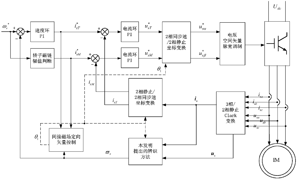
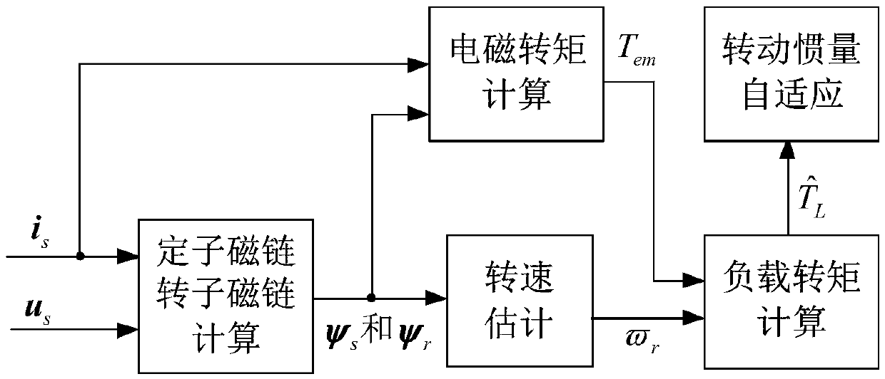
[0039] The indirect magnetic field oriented vector control method is adopted, including voltage and current sensors, and an indirect magnetic field oriented controller. The identification method implementation module proposed by the present invention, and the voltage sinusoidal pulse width modulation module are shown in figure 1 shown. The present invention mainly relates to moment of inertia identification and speed estimation, the specific structure is shown in figure 2 As shown; other modules are functional modules required for vector control of induction motors, which are existing technologies and common knowledge in this field.

[0040] The workflow of the whole ...


PUM


Abstract

The present invention relates to the field of motor control, especially to a method for identifying a rotational inertia transient state of an induction motor. The method is used for vector control ofan induction motor in an operation condition of a speed sensorless. The current identification method is too large in computing amount and cannot meet the requirement of accurate estimation of the transient state. The method provided by the invention comprises the following steps in order: (1) detecting a three-phase stator voltage and current, and respectively marking the voltage and the currentas a vector us and a vector is; (2) according to a [gamma]-type equivalent circuit, calculating a stator flux and a rotor flux; (3) calculating the electromagnetic torque; (4) calculating a rotationspeed; (5) filtering the calculated rotation speed signals; (6) calculating a load torque; and (7) constructing the adaptive identification of the rotational inertia transient state. The rotational inertia information is extracted in the transient state torque signals, and the method provided by the invention can be employed in the induction motor transient state process; the identification of therotational inertia transient state can be achieved with no need for a speed sensorless to improve the operation dynamic performance of the speed sensorless; and moreover, the computing steps are simple and the process computing amount is small.

Description

technical field [0001] The invention relates to the field of motor control, in particular to a moment of inertia transient identification method of an induction motor, which is used for vector control of the induction motor under the condition of no speed sensor operation. Background technique [0002] Induction motors running without a speed sensor are widely used in industry today to avoid the acquisition cost, maintenance cost and installation space required to install a mechanical speed sensor. The difficulty of high-performance control of induction motors in the current speed sensorless operation mode is how to make real-time identification of motor parameters such as moment of inertia, stator and rotor resistance, etc. under the transient operating conditions of motor acceleration and deceleration. Although some existing speed sensorless algorithms can make more accurate speed estimation when the motor is running in a steady state, the calculation error in the transien...

Claims


Application Information

Patent Timeline
Patent Type & Authority Applications(China)
IPC IPC(8): H02P21/14
CPCH02P21/143
Inventor 赵力航陈嘉豪杨敏陈新琪王新汪洋叶赵慧勉
Owner ZHEJIANG ZHENENG TECHN RES INST
Why Eureka
Try Eureka