
A special mold for small catheter tip machine

The technology of a pointed machine and a small catheter is applied in the field of advanced small catheter processing equipment, which can solve the problems of long processing time, low processing efficiency, hidden dangers of production accidents, etc., and achieve the effects of good finished product quality, high processing efficiency and good versatility

Active Publication Date: 2021-01-12
佛山市顺德区精和模具配件有限公司
View PDF9 Cites 0 Cited by
  • Summary
  • Abstract
  • Description
  • Claims
  • Application Information

AI Technical Summary

Problems solved by technology

In the existing tip grinding equipment for advanced small catheters, induction heating is often required. After heating, manual grinding or cutting on a machine tool is very low in processing efficiency. At the same time, if cutting is used, there will be a lot of broken Chips, the tool is easy to wear when heated, after the tool is worn, it is difficult to guarantee the processing quality, and it is difficult to guarantee the quality of the finished product
This leads to the fact that in the prior art, the tapering process takes a long time, and it is easy to cause the tip and the tube body to be out of center, resulting in unsatisfactory processing effect.
This requires the design of equipment specially used for the processing of small catheter tips. Although there are devices on the market that use perforations in the processing disc to process small catheter tips, the perforation of the processing disc is a fixed structure. After the small catheter is inserted, it is easy to get stuck, there is a great hidden danger of production accidents, and the processing quality cannot be reliably guaranteed

Method used


Image

  • A special mold for small catheter tip machine
  • A special mold for small catheter tip machine
  • A special mold for small catheter tip machine

Examples


Embodiment Construction

[0026] It should be noted that, in the case of no conflict, the embodiments of the present invention and the features in the embodiments can be combined with each other.

[0027] Specific embodiments of the invention will be described in detail below.

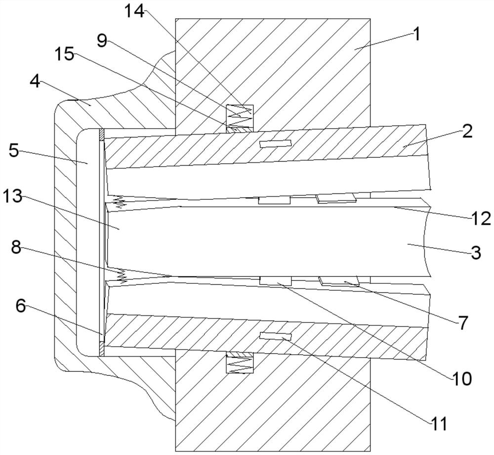
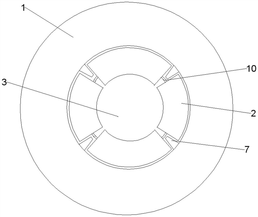
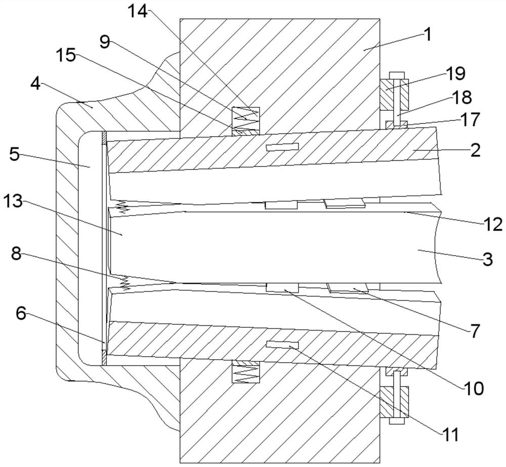
[0028] A special mold for a small catheter tip machine, such as Figures 1 to 4 As shown, it includes a base 1 and a molding die in the base; the molding die is composed of several petal mold bodies 2, forming a molding cavity 3 with a tapered structure inside the molding die; in order to ensure the stability of the overall structure of the mold, the mold The distance between the maximum gap between the body and the inner wall of the base mounting hole is 2-5mm. Such a structural arrangement can ensure the stability of the mold to the greatest extent during the pointed head processing, so that the distance between the mold bodies is not too large and avoids large gaps. Abnormal fluctuations in amplitude.

[0029] The rear end...


PUM


Abstract

The invention provides a special mold for a small guide pipe pointed head machine. A base and a forming mold in the base are included; the forming mold is composed of a plurality of sections of mold bodies; a forming cavity of a conical structure is formed in the forming mold; a tail base is arranged at the rear end of the base; a conical installing hole is formed in the base, and an inner cavitycorresponding to the installing hole is formed in the tail base; the inner wall of the tail base is provided with positioning plates for limiting the mold bodies; the inner wall of an installing portion is provided with a plurality of partition plates; each mold body is correspondingly installed between the two corresponding two partition plates; a first holding part is arranged between every twoadjacent mold bodies; and the portion, corresponding to each mold body, on the base is provided with a second holding part. The special mold for the small guide pipe pointed head machine is simple instructure, reasonable in design, and applicable to machining of small guide pipe pointed heads in various specifications, the forming cavity of the forming mold can also be fixed into a certain special shape according to the designing and using requirement, the special machining requirement is met, universality is good, the machining efficiency is high, and the finished product quality is good.

Description

technical field [0001] The invention belongs to the technical field of advanced small catheter processing equipment, and in particular relates to a special mold for a small catheter tip machine. Background technique [0002] With the widespread use of tunnels, the amount of advanced small catheters is increasing, and the advanced small catheters need to be drilled and tapered. In the existing tip grinding equipment for advanced small catheters, induction heating is often required. After heating, manual grinding or cutting on a machine tool is very low in processing efficiency. At the same time, if cutting is used, there will be a lot of broken Chips, the tool is easy to wear when heated, after the tool is worn, it is difficult to guarantee the processing quality, and it is difficult to guarantee the quality of the finished product. As a result, in the prior art, the tapering process takes a long time, and it is easy to cause the tip and the tube body to be out of center, re...

Claims


Application Information

Patent Timeline
Patent Type & Authority Patents(China)
IPC IPC(8): B21D41/04B21D37/10
CPCB21D37/10B21D41/04
Inventor 冯光芬
Owner 佛山市顺德区精和模具配件有限公司
Learn More