Polishing buffing device for machine manufacturing

A polishing device and mechanical manufacturing technology, applied in the direction of grinding/polishing equipment, manufacturing tools, surface polishing machine tools, etc., can solve problems such as not being suitable for large-scale production, affecting the effect of grinding and polishing, and difficult to control the strength, etc., to achieve High grinding efficiency, good effect, enhanced effect

Inactive Publication Date: 2019-04-23
JINGDEZHEN CERAMIC INSTITUTE
View PDF5 Cites 8 Cited by
  • Summary
  • Abstract
  • Description
  • Claims
  • Application Information

AI Technical Summary

Problems solved by technology

[0003] At present, in the field of grinding and polishing, the most widely used method is manual hand polishing machine, which performs grinding and polishing on fixed machined p

Method used


Image

  • Polishing buffing device for machine manufacturing
  • Polishing buffing device for machine manufacturing
  • Polishing buffing device for machine manufacturing

Examples


Embodiment 1

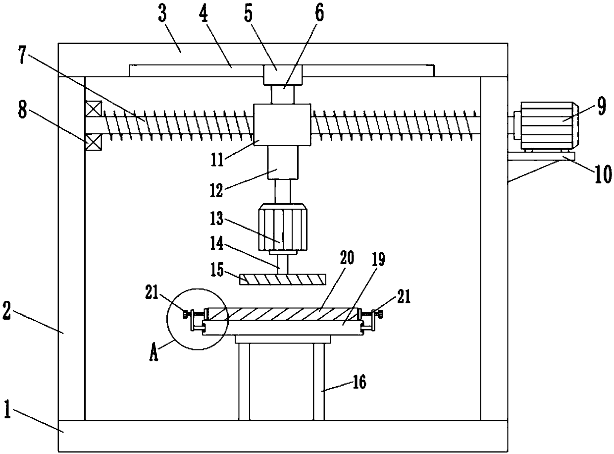
[0022] See Figure 1~3 In the embodiment of the present invention, a grinding and polishing device for machine manufacturing includes a bottom plate 1, a side plate 2 and a top plate 3. Both sides of the bottom plate 1 are vertically fixed with a side plate 2, and two side plates 2 A top plate 3 is fixedly connected to the top, the top plate 3 is provided with a sliding groove 4, a first sliding block 5 is slidably installed in the sliding groove 4, and a screw rod 7 is horizontally arranged under the top plate 3, and one end of the screw rod 7 passes The bearing seat 8 is rotatably connected to a side plate 2. The other end of the screw rod 7 passes through the other side plate 2 and is connected to the output end of the first motor 9, and the first motor 9 is installed on the side of the side plate 2 through a bracket 10 , The screw rod 7 is provided with a second slider 11, a connecting piece 6 is fixedly connected between the second slider 11 and the first slider 5, and the...

Embodiment 2

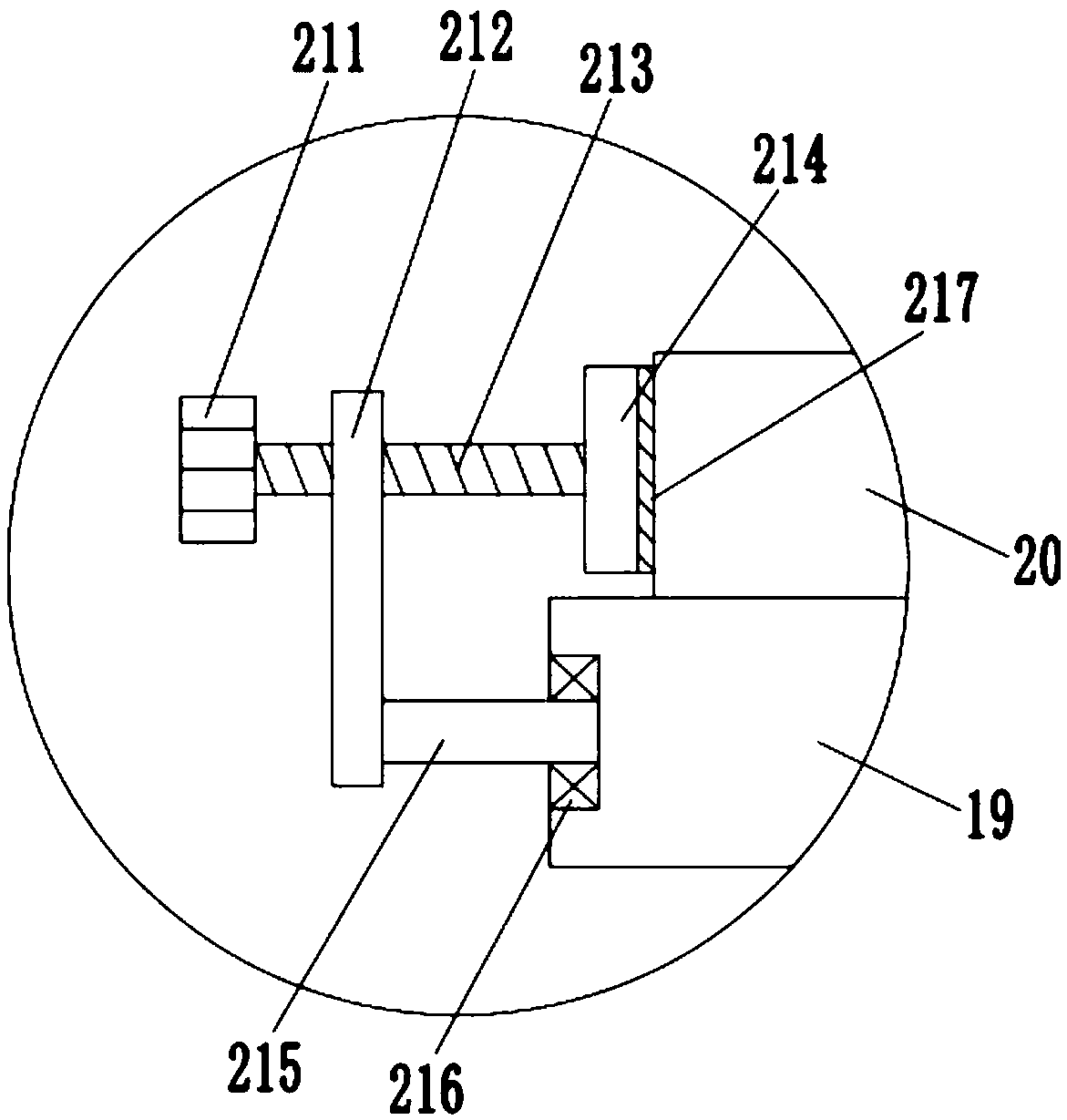
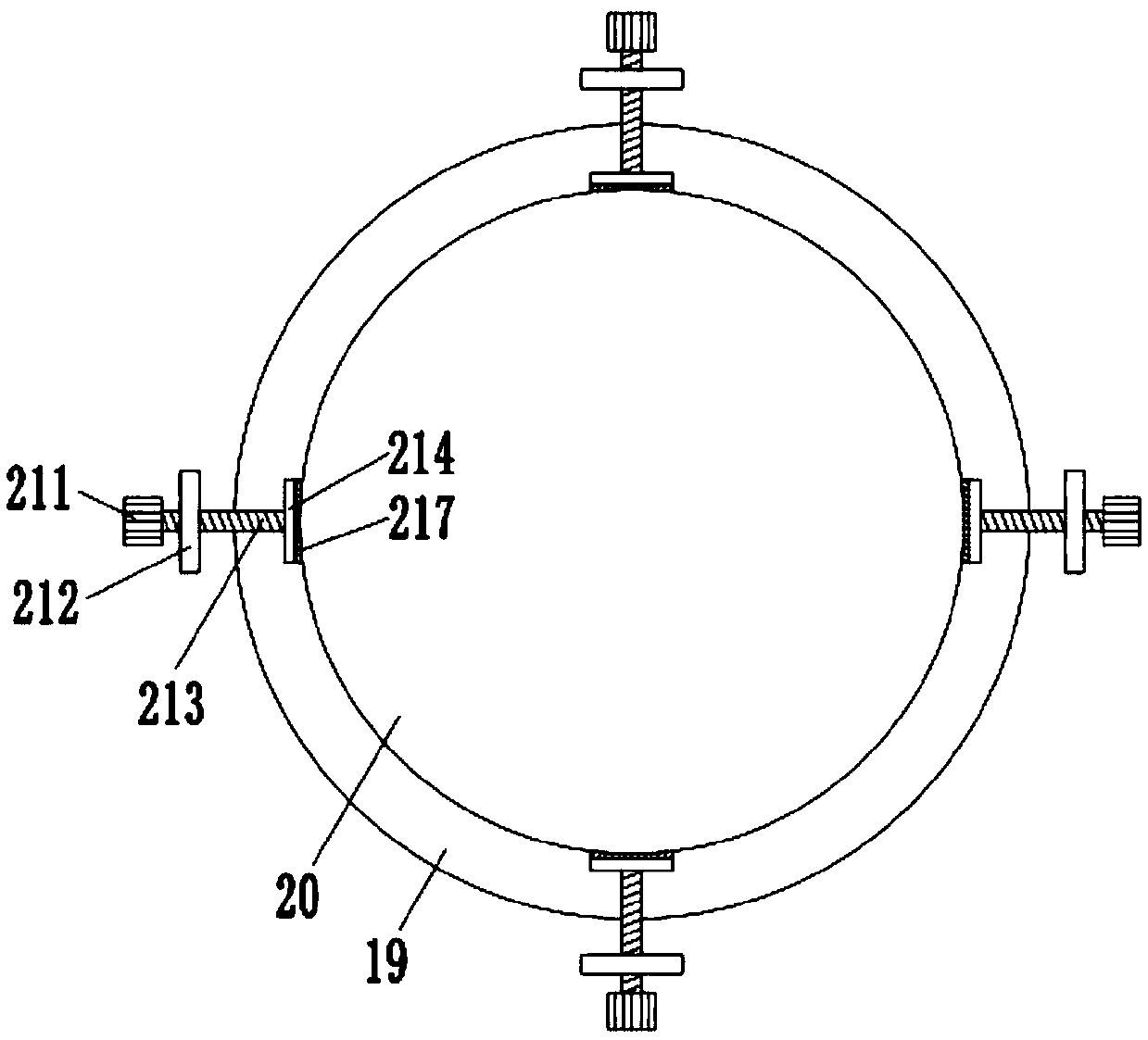
[0028] See Figure 1~3 This embodiment is mainly a further upgrade of the clamping device 21 on the basis of the first embodiment, that is, the clamping device 21 includes a knob 211, a vertical plate 212, a screw 213, a pressure plate 214 and a connecting rod 215, and the connection The rod 215 is horizontally connected to the side of the pallet 19, and the end of the connecting rod 215 away from the pallet 19 is connected to a vertically arranged vertical plate 212. The vertical plate 212 passes through a threaded screw 213. Both ends of the screw 213 The knob 211 and the pressing plate 214 are respectively connected, and the pressing plate 214 is pressed against the side surface of the workpiece 20.

[0029] When the clamping device 21 is used to clamp and fix the workpiece 20, it is only necessary to rotate the screw 213 inward through the knob 211, and the screw 213 drives the pressure plate 214 to move inward until it touches the side of the workpiece 20, thereby realizing ...

Embodiment 3

[0033] See Figure 4 This embodiment is mainly a further upgrade on the basis of the second embodiment, that is, a third motor 17 is added between the support plate 19 and the support plate 16 to enhance the polishing effect of the workpiece 20. The support plate 19 A third motor 17 is arranged between the support plate 16 and the output end of the third motor 17 is connected with a third rotating shaft 18, and the top end of the third rotating shaft 18 is fixedly connected to the bottom center of the supporting plate 19.

[0034] Further, the third motor 17 is a servo motor.

[0035] Here, by controlling the third motor 17 and the second motor 13 to rotate in opposite directions, the workpiece 20 can be rotated and polished, which effectively enhances the polishing effect and improves work efficiency.


PUM


Abstract

The invention discloses a polishing buffing device for machine manufacturing, and belongs to the technical field of polishing buffing. The polishing buffing device comprises a bottom plate, side plates and a top plate; the side plates are fixedly connected to the two sides of the bottom plate; the top plate is fixedly connected to the tops of the two side plates; a screw rod is horizontally arranged under the top plate, one end of the screw rod is rotationally connected with one side plate through a bearing seat, and the other end of the screw rod penetrates through the other side plate to beconnected with a first motor; a second slide block is arranged on the screw rod in a matched mode; an air cylinder is vertically installed at the bottom of the second slide block, a second motor is installed at the telescopic end of the air cylinder, and a buffing wheel is installed at the output end of the second motor through a second rotary shaft; and a supporting plate is installed on the bottom plate through a support frame, and a workpiece is placed on the supporting plate. According to the polishing buffing device provided by the invention, compared with a common polishing buffing device, the screw is driven to rotate through the first motor, horizontal moving of the buffing wheel can be achieved, the buffing wheel is driven to conduct polishing buffing through the second motor, time and labor are saved, in addition, the polishing efficiency is high, and the polishing effect is good.

Description

Technical field [0001] The invention relates to the technical field of grinding and polishing, in particular to a grinding and polishing device for machine manufacturing. Background technique [0002] With the development of the machinery industry, customers have higher and higher requirements for the surface quality of parts, and grinding and polishing are more and more widely used in industrial and civilian products. Polishing refers to the use of mechanical, chemical or electrochemical effects to reduce the surface roughness of the workpiece to obtain a bright, smooth surface. In the machinery manufacturing industry, the most common is to use polishing tools and abrasive particles or other polishing media to modify the surface of the workpiece, which cannot improve the dimensional accuracy of the workpiece, but aims to obtain a smooth surface or mirror gloss. [0003] At present, in the field of polishing and polishing, the most widely used method is manual hand polishing machi...

Claims


Application Information

Patent Timeline
IPC IPC(8): B24B29/00B24B41/06
Inventor 潘玉安
Owner JINGDEZHEN CERAMIC INSTITUTE
Why Eureka
Try Eureka