Aluminum foil cutting equipment and cutting method

A technology for cutting equipment and aluminum foil, which is applied in metal processing and other directions, can solve the problems of high friction between the cutting knife and aluminum foil, increase the stress of the aluminum film, and low cutting efficiency, so as to avoid stress changes, reduce the cutting temperature, and improve the cutting effect. Effect

Inactive Publication Date: 2019-04-23
佛山市中技烯米新材料有限公司
View PDF9 Cites 0 Cited by
  • Summary
  • Abstract
  • Description
  • Claims
  • Application Information

AI Technical Summary

Problems solved by technology

[0005] In the existing aluminum foil cutting equipment, the cutting knife is fixed on the support seat, and the aluminum foil is rolled by the roller. The friction between the cutting knife and the aluminum foil is large, the cutting surface of the aluminum foil is rough, and the aluminum foil is easy to tear, and the cutting efficiency is low.
In addition, the friction between the cutting line and the aluminum foil is high, and the cutting surface temperature of the aluminum foil is high, which will increase the stress of the aluminum film, affect the subsequent coating of silica gel, and then affect the quality of the silica gel film

Method used


Image

  • Aluminum foil cutting equipment and cutting method
  • Aluminum foil cutting equipment and cutting method
  • Aluminum foil cutting equipment and cutting method

Examples


Embodiment Construction

[0031] In order to make the object, technical solution and advantages of the present invention clearer, the present invention will be further described in detail below in conjunction with the accompanying drawings.

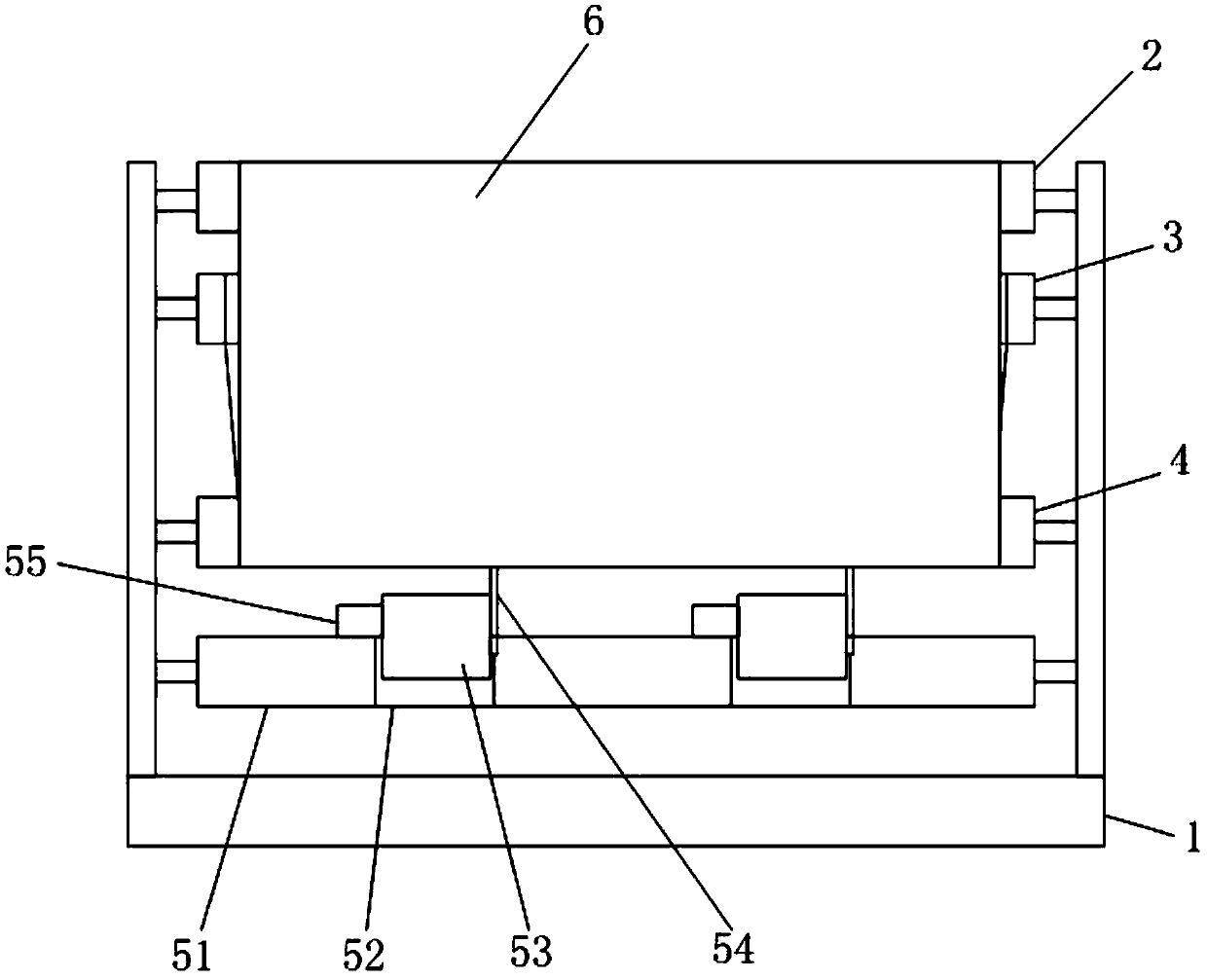
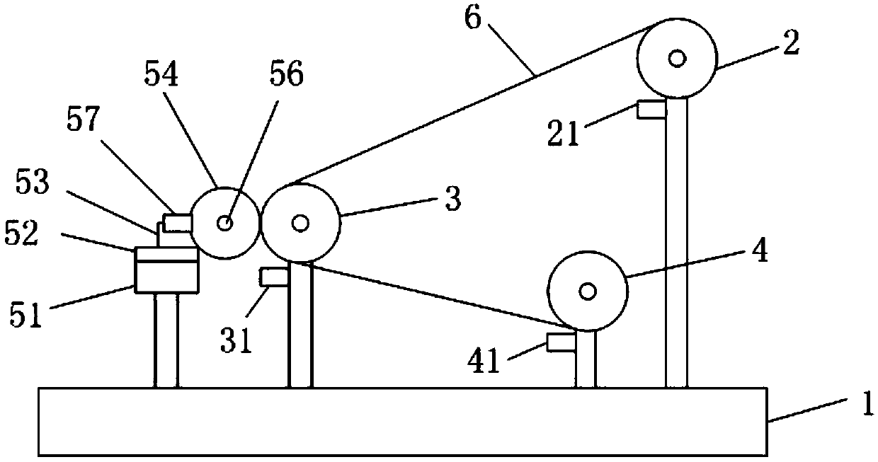
[0032] see figure 1 and figure 2 , an aluminum foil cutting equipment provided by the present invention includes a frame 1, a first roller 2, a second roller 3, a third roller 4 and a cutting device.

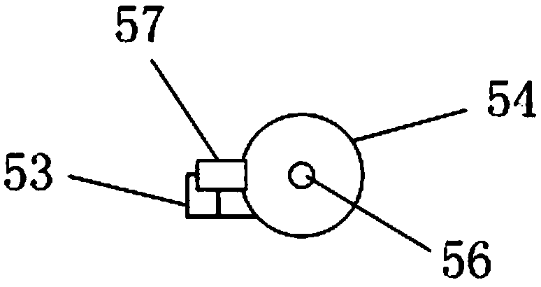
[0033] The cutting device comprises a slide rail 51 arranged on the frame, a slide block 52 slidably connected on the slide rail 51, a fixed seat 53 arranged on the slide block 52, a round knife 54 connected on the fixed seat 53, and The first driving device 55 that drives the circular knife 54 to rotate. The round knife 54 of the present invention is rotatably connected to the fixed seat 53 through the rotating shaft 56, but it is not limited thereto. Wherein, the first driving device 45 is connected with the rotating shaft 56 to drive the circular knife 54 to ...


PUM


Abstract

The invention discloses aluminum foil cutting equipment. The aluminum foil cutting equipment comprises a rack, a first rolling shaft, a second rolling shaft, a third rolling shaft and a cutting device; the cutting device comprises a sliding rail, a slider, a fixing seat, a circular knife and a first driving device, wherein the sliding rail is arranged on the rack; the slider is slidably connectedto the sliding rail; the fixing seat is arranged on the slider; the circular knife is connected to the fixing seat; the first driving device is used for driving the circular knife to rotate; the sliding rail is arranged at one side of the second rolling shaft; the edge of the circular knife makes contact with an aluminum foil positioned on the second rolling shaft; the second rolling shaft is connected with a second driving device; the linear speed of the circular knife is the same as that of the aluminum foil on the second rolling shaft; the first rolling shaft is provided with an aluminum foil raw material; the aluminum foil sequentially passes through the second rolling shaft and the third rolling shaft from the first rolling shaft; and the third rolling shaft is used for re-rolling thealuminum foil which is cut. Correspondingly, the invention further discloses an aluminum foil cutting method. The aluminum foil cutting equipment disclosed by the invention is simple in structure, the cut surface of the aluminum foil is smooth, and a good cutting effect is achieved.

Description

technical field [0001] The invention relates to the technical field of cutting equipment, in particular to an aluminum foil cutting equipment and a cutting method. Background technique [0002] With the development of our country's economy and the continuous improvement of people's living standards, the requirements for ambient air quality are also increasing. An energy-saving ventilation system is being developed and utilized. Up to now, the runner and adsorption materials have developed to the fourth generation. , using advanced solid adsorption technology, it can operate continuously and stably with large-load air humidity control, especially in low-temperature and low-humidity conditions, it can achieve an ultra-low air dew point of -70°C. At present, the adsorption and separation of air solids mainly adopts the turntable metal adsorption body. During the dehumidification process, the adsorption turntable rotates slowly under the drive of the driving device. When the ads...

Claims


Application Information

Patent Timeline
IPC IPC(8): B26D1/22B26D5/08B26D7/08B26D7/32
CPCB26D1/225B26D5/086B26D7/088B26D7/32
Inventor 刘福海
Owner 佛山市中技烯米新材料有限公司
Why Eureka
Try Eureka