
3D printing charging tray and exposure stripping technology of 3D printing charging tray

A 3D printing and material tray technology, applied in the field of 3D printing, can solve the problems of difficult peeling of photosensitive materials, affecting printing accuracy, and inability to form a tensioned release film plane, etc., to improve printing accuracy, strong practicability, and simple structure. Effect

Pending Publication Date: 2019-04-23
GUANGZHOU HEIGE ZHIZAO INFORMATION TECH CO LTD
View PDF6 Cites 10 Cited by
  • Summary
  • Abstract
  • Description
  • Claims
  • Application Information

AI Technical Summary

Problems solved by technology

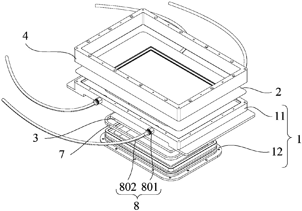
[0005] The purpose of this application is to provide a 3D printing material tray and the exposure stripping process of the 3D printing material tray, which solves the problem that the 3D printing material tray in the prior art cannot form a tensioned release during the working process to a certain extent. The plane of the film, which affects the printing accuracy, and the technical problem of difficult peeling of photosensitive materials after exposure in the prior art

Method used


Image

  • 3D printing charging tray and exposure stripping technology of 3D printing charging tray
  • 3D printing charging tray and exposure stripping technology of 3D printing charging tray
  • 3D printing charging tray and exposure stripping technology of 3D printing charging tray

Examples


Embodiment Construction

[0033] The technical solutions of the present application will be clearly and completely described below in conjunction with the accompanying drawings. Apparently, the described embodiments are some of the embodiments of the present application, not all of them.

[0034] The components of the embodiments of the application generally described and shown in the figures herein may be arranged and designed in a variety of different configurations. Accordingly, the following detailed description of the embodiments of the application provided in the accompanying drawings is not intended to limit the scope of the claimed application, but merely represents selected embodiments of the application.

[0035] Based on the embodiments in this application, all other embodiments obtained by persons of ordinary skill in the art without making creative efforts belong to the scope of protection of this application.

[0036]In the description of this application, it should be noted that the term...


PUM


Abstract

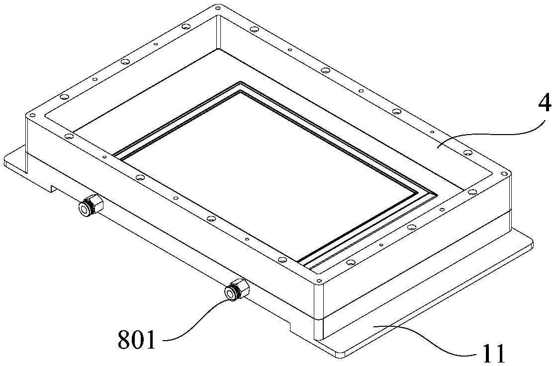
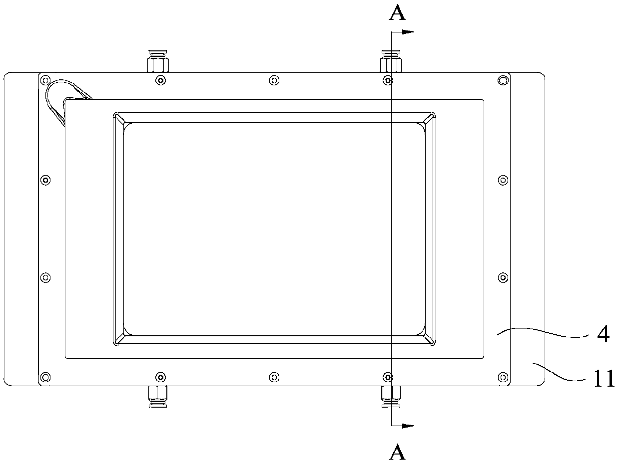
The invention relates to the technical field of 3D printing, in particular to a 3D printing charging tray and an exposure stripping technology of the 3D printing charging tray. The 3D printing charging tray comprises a base, a releasing film, light-transmitting glass and a clamping plate. The base is provided with a first groove and a second groove, the first groove and the second groove penetratethrough the top end face of the base, the light-transmitting glass is arranged in the first groove, the upper surface of the light-transmitting glass is higher than the bottom wall face of the secondgroove, the release film is arranged on the top end face of the base and is pressed between the base and the clamping plate, a first cavity is defined by the release film, the inner wall of the firstgroove and the light-transmitting glass, a second cavity is defined by the release film and the inner wall of the second groove, and the two cavities communicate. During exposure, the cavities are pumped to from negative pressure, the release film can be tightly attached to the glass, bubbles do not exist between the release film and the glass, tensioning of the release film is achieved, the printing precision is improved, when the release film is released, air is inflated to the cavities, the cavities form positive pressure, the release film and the light-transmitting glass are stripped, andthe aim is easily achieved.

Description

technical field [0001] The present application relates to the technical field of 3D printing, in particular to a 3D printing tray and an exposure stripping process for the 3D printing tray. Background technique [0002] At present, with the advancement of light-curing 3D printing technology, light-curing 3D printers are also developing towards industrial machines. As a tray carrying photosensitive materials, the professional requirements are getting higher and higher. The more common ones are the film-coated trays made of silica gel and the stretch film trays that use the structure to tension the release film. [0003] Common film-coated trays are composed of structural parts, light-transmitting glass, silica gel, and release film. Use glue to fix the light-transmitting glass on the structural parts and achieve a sealing effect. Pour the adjusted liquid silica gel onto the light-transmitting glass and scrape it flat and wait for it to solidify naturally. Finally, stick t...

Claims


Application Information

Patent Timeline
IPC IPC(8): B29C64/20B29C64/255B29C64/124B33Y30/00B33Y10/00
CPCB29C64/124B29C64/20B29C64/255B33Y10/00B33Y30/00
Inventor 黄鹤源邢永锋蔡德信桂培炎武让
Owner GUANGZHOU HEIGE ZHIZAO INFORMATION TECH CO LTD
Learn More