Dynamic two-dimensional stage laser lamp

A laser light and stage technology, applied in the field of dynamic two-dimensional stage laser light, can solve the problems of monotonous artistic performance effect and difficulty in satisfying atmosphere rendering, and achieve the effect of rich styles and improved projection range.

Inactive Publication Date: 2019-04-23
沈炜
View PDF6 Cites 0 Cited by
  • Summary
  • Abstract
  • Description
  • Claims
  • Application Information

AI Technical Summary

Problems solved by technology

However, this kind of laser light can only project one or more light spots on the scene, that is, only a few light spots can be moved on the scene, and its artistic expression effect is relatively monotonous. In the case of a small number of laser lights, it is difficult to satisfy large Ambient Rendering of the Range

Method used


Image

  • Dynamic two-dimensional stage laser lamp
  • Dynamic two-dimensional stage laser lamp
  • Dynamic two-dimensional stage laser lamp

Examples


Embodiment 1

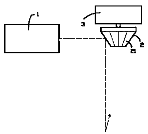
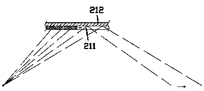
[0015] exist figure 1 , figure 2 In the first embodiment shown, the dynamic two-dimensional stage laser light includes a laser downlight 1 that can project a laser line forward; At most pyramid 2; as figure 1 As shown by the middle dotted line, the laser line of the laser downlight 1 is irradiated obliquely to the side surface of the flat-topped polygonal pyramid 2; figure 2 As shown, it includes an outer layer of liquid crystal sheet 211 and an inner layer of flat lens 212; the liquid crystal sheet 211 is controlled by a control module (not shown), so that any position of the liquid crystal sheet 211 can appear black or transparent; The patterns displayed on the liquid crystal panels 211 are rotationally symmetrical about the axis of the flat-topped polygonal pyramid 2 ; that is, the patterns displayed on each liquid crystal panel 211 are exactly the same.

[0016] The above dynamic 2D stage laser lights, such as figure 1 As shown, in the case where the entire surface o...

Embodiment 2

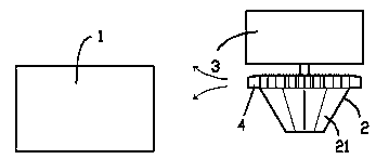
[0019] for image 3 The second embodiment shown is different from the first embodiment in that an impeller 4 is formed at the end of the flat-topped polygonal pyramid 2 close to the driving motor 3. A heat-dissipating airflow is formed near the downlight 1; thus, the heat-dissipating performance of the laser downlight 1 is improved.

Embodiment 3

[0021] for Figure 4 The third embodiment shown is different from the first embodiment in that a polygonal column 5 driven by a servo motor 6 is arranged in front of the flat-top polygonal pyramid 2, and the axis of the polygonal column 5 is parallel to the The axis of the top polygonal pyramid 2 is orthogonal, and the side surfaces of the polygonal prism 5 are formed by mirror surfaces; such as Figure 4 As shown by the middle dotted line, the laser light reflected by the flat-topped polygonal pyramid 2 is first irradiated to the side surface of the polygonal prism 5 , and then reflected by the side surface of the polygonal prism 5 and projected to the scene. Therefore, the laser line formed by the rotation of the flat-topped polygonal pyramid 2 will traverse on the site after the rotation of the polygonal column 5, so that the original laser spot can be expanded horizontally and vertically in the on-site area. Randomly changing laser color blocks; if the original laser spot...


PUM


Abstract

The invention provides a dynamic two-dimensional stage laser lamp. The dynamic two-dimensional stage laser lamp comprises a laser down lamp capable of projecting laser rays forwards; a flat top polygonal prism is arranged in front of the laser down lamp and driven by a driving motor to rotate around the axis of the flat top polygonal prism, and laser rays of the laser down lamp obliquely irradiatethe side face of the flat top polygonal prism; the side face of the flat top polygonal prism is composed of electronic reflective mirrors, and the electronic reflective mirrors comprise outer layer liquid crystal pieces and inner layer planar mirror pieces; the liquid crystal pieces are controlled by a control module so that any position of the liquid crystal pieces can be black or transparent; patterns presented on all the liquid crystal pieces are in rotary symmetry around the axis of the flat top polygonal prism. The dynamic two-dimensional stage laser lamp can form dynamic line shapes orplanar projections on a scene, so that the rendering range is substantially enlarged.

Description

[0001] This application is a divisional application of the patent application with the application number of 201710469008.6 and the name is stage laser light. technical field [0002] The invention relates to the field of stage lighting equipment, in particular to a dynamic two-dimensional stage laser light. Background technique [0003] In the field of stage lighting, laser light is a commonly used lighting fixture, which is mainly used to render the scene atmosphere. The current dynamic two-dimensional stage laser light mainly includes a lamp holder and a laser lamp canister. The lamp holder and the laser lamp canister are connected by a controllable shaft driven by a drive motor, so that the laser line emitted by the laser canister can move on the spot. However, this kind of laser light can only project one or more light spots on the scene, that is, only a few light spots can be moved on the scene, and its artistic expression effect is relatively monotonous. Range of atm...

Claims


Application Information

Patent Timeline
Patent Type & Authority Applications(China)
IPC IPC(8): F21S10/00F21V14/06F21V7/00F21V23/00F21V21/15F21W131/105F21W131/406F21Y115/30
CPCF21S10/00F21V7/00F21V14/06F21V21/15F21V23/003F21W2131/105F21W2131/406F21Y2115/30
Inventor 沈炜
Owner 沈炜
Why Eureka
Try Eureka