Grid drive unit and drive method thereof, grid drive circuit and display device

A gate drive and gate technology, which is applied to gate drive circuits, display devices, gate drive units and their driving fields, can solve the problem of gate potential pull of output transistors and so on.

Active Publication Date: 2019-04-23
HEFEI XINSHENG OPTOELECTRONICS TECH CO LTD +1
View PDF8 Cites 8 Cited by
  • Summary
  • Abstract
  • Description
  • Claims
  • Application Information

AI Technical Summary

Problems solved by technology

[0003] Among them, the clock signal terminal directly provides the output transistor with a clock signal switched between high and low levels, and since the output transistor itself has a certain capacitance, after the output stage, when the clock signal terminal reaches a high level, the output transistor’s The gate potential will be pulled up slightly, so that the second pole of the output transistor will output a certain signal, thereby generating a certain amount of noise

Method used


Image

  • Grid drive unit and drive method thereof, grid drive circuit and display device
  • Grid drive unit and drive method thereof, grid drive circuit and display device
  • Grid drive unit and drive method thereof, grid drive circuit and display device

Examples


Embodiment Construction

[0065] Specific embodiments of the present invention will be described in detail below in conjunction with the accompanying drawings. It should be understood that the specific embodiments described here are only used to illustrate and explain the present invention, and are not intended to limit the present invention.

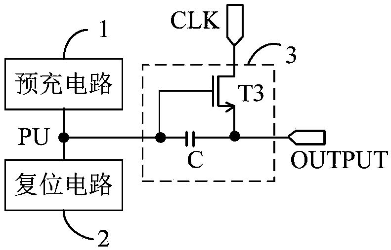
[0066] figure 1 It is a structural schematic diagram of an existing shift register, such as figure 1 As shown, the shift register includes a precharge circuit 1, a reset circuit 2 and an output circuit 3, and the output circuit 3 includes an output transistor T3 and a capacitor C. The pre-charging circuit 1, the reset circuit 2 and the output circuit 3 are connected to the pull-up node PU, and the output transistor T3 is directly connected to the clock signal terminal CLK. In the pre-charging stage, the pre-charging circuit 1 charges the pull-up node PU; the output transistor T3 transmits the invalid signal of the clock signal terminal to the output terminal O...


PUM


Abstract

The invention provides a grid drive unit, which comprises a shifting register and a signal filter, wherein the shifting register comprises a first pre-charging circuit, an output circuit and a first reset circuit; the signal filter is used for transmitting a signal at a clock signal end to a screening output end under the control of an effective signal provided by an input end after the input endstops providing the effective signal and before a reset end provides the effective signal, and disconnecting the clock signal end and the screening output end under the control signal provided by thereset end; the first pre-charging circuit is used for pre-charging a first pull-up node under the control of the effective signal provided by the input end; and the output circuit is used for transmitting the signal of the screening output end to the signal output end when the first pull-up node is at an effective potential. The invention further provides a drive method of the grid drive unit, a grid drive circuit and a display device. According to the grid drive unit and the drive method thereof, the grid drive circuit and the display device, the noise of the grid drive unit can be reduced.

Description

technical field [0001] The present invention relates to the field of display technology, in particular to a gate drive unit, a drive method thereof, a gate drive circuit, and a display device. Background technique [0002] The gate driving circuit of the display device includes a plurality of cascaded shift registers, and the plurality of shift registers sequentially output scanning signals. The shift register includes an output transistor, the gate of the output transistor is connected to the pull-down node, the first pole of the output transistor is connected to the clock signal terminal, and the second pole of the output transistor is connected to the output terminal of the shift register unit. In the input phase and output phase of the shift register unit, the output transistor is turned on under the control of the potential of the pull-up node, so that the signal at the clock signal terminal is directly transmitted to the output terminal of the shift register through th...

Claims


Application Information

Patent Timeline
Patent Type & Authority Applications(China)
IPC IPC(8): G09G3/20G11C19/28
CPCG09G3/20G11C19/28G09G2310/0286G09G3/3266G09G3/3674G09G2300/0408G09G2310/0267G09G2300/0426G09G2310/08G09G2330/02G09G3/2092
Inventor 牟广营周纪登邹宜峰吕凤珍
Owner HEFEI XINSHENG OPTOELECTRONICS TECH CO LTD
Why Eureka
Try Eureka