Power assisting device and power assisting bicycle

A technology of power-assisted bicycles and power-assisted devices, which is applied to chain/belt transmission devices, vehicle components, vehicle gearboxes, etc., which can solve the problems of lower device reliability, short center distance, and increased maintenance costs, and achieve isolation from muddy water and sewage material, improve service life, and avoid improper consumption

Pending Publication Date: 2019-04-26
南京奥特博机电科技有限公司
View PDF8 Cites 2 Cited by
  • Summary
  • Abstract
  • Description
  • Claims
  • Application Information

AI Technical Summary

Problems solved by technology

[0003] However, through long-term use of the product, it has been found that in the technical solution disclosed in the above-mentioned patent, the pedal force measuring device, the first sprocket, the chainring and the auxiliary wheel are all exposed outside the casing, which causes many problems:
[0004] 1. Due to the chain transmission driving method, relatively large noise is generated during the transmission process, which in turn has a certain adverse effect on the rider and the surrounding crowd
[0005] 2. Since the transmission parts need to be lubricated with lubricating oil, but the completely exposed setting method will accelerate the consumption of lubricating oil, resulting in the transmission parts not being lubricated effectively for a long time, accelerating the loss of parts, reducing the reliability of the device and increasing maintenance costs
[0006] 3. Due to the relatively short center distance between transmission components such as the tooth plate, the first sprocket and the auxiliary wheel, once the vehicle passes through the muddy road, the dirt attached to the chain or belt may be deposited between these sprockets, causing Faults such as transmission failure reduce the reliability of the device, which not only seriously affects the riding experience, but also increases maintenance costs

Method used


Image

  • Power assisting device and power assisting bicycle
  • Power assisting device and power assisting bicycle
  • Power assisting device and power assisting bicycle

Examples


Embodiment 1

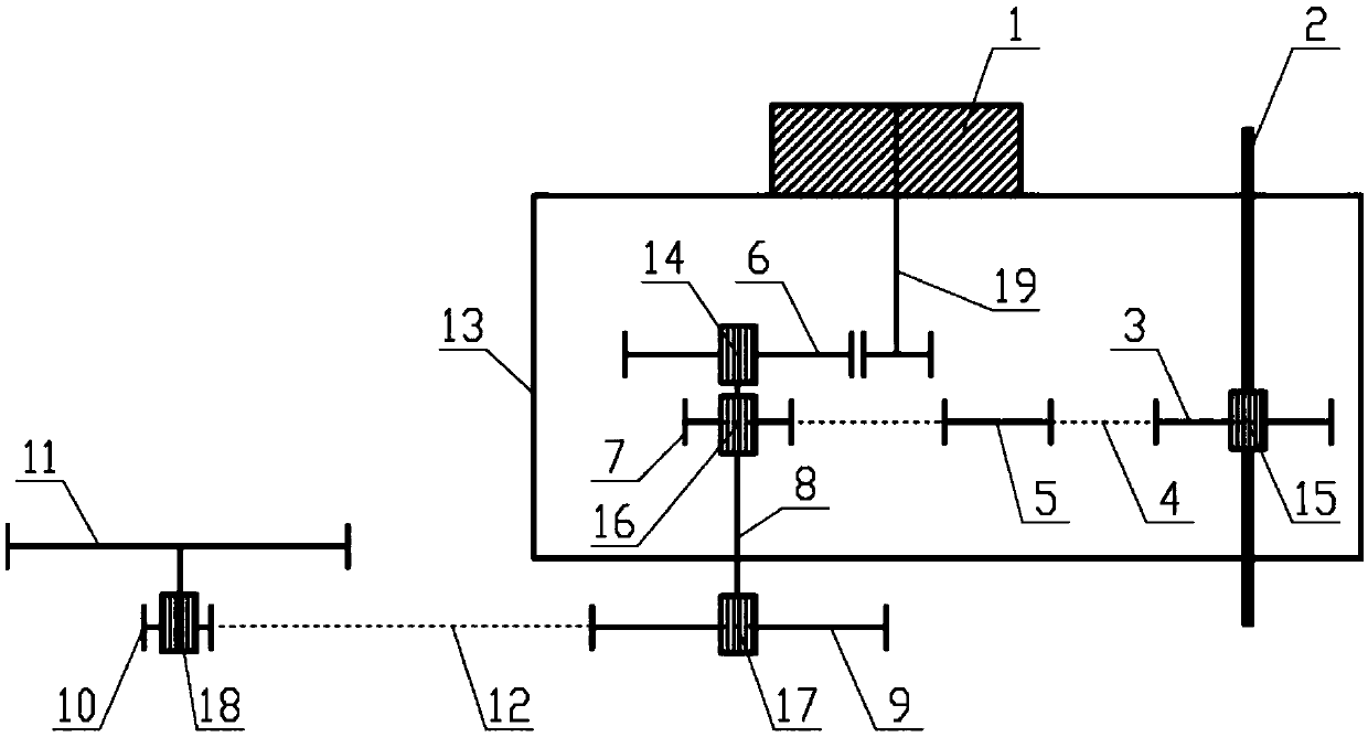
[0059] Such as figure 1 , 6 , 7 and 8, the booster device of the present invention includes a crankshaft 3, a drive shaft 8, a flywheel 10, a first drive wheel 7, a second drive wheel 9 and a pedal force measuring device (not shown), a motor 1 and motor controller 27.

[0060] A transmission connection is established between the tooth plate 3 and the first driving wheel 7 through the first chain 4, and the transmission connection between the second driving wheel 9 and the flywheel 10 is established through the second chain 12 or the second belt (not shown). The first driving wheel 7 and the second drive wheel 9 are all installed on the drive shaft 8, and the torque on the first drive wheel 7 can act on the second drive wheel 9.

[0061] The chainring 3 , the first chain 4 , the first driving wheel 7 and the pedal force measuring device are all integrated in a housing 13 , and the second driving wheel 9 , the second chain 12 and the flywheel 10 are arranged outside the housin...

Embodiment 2

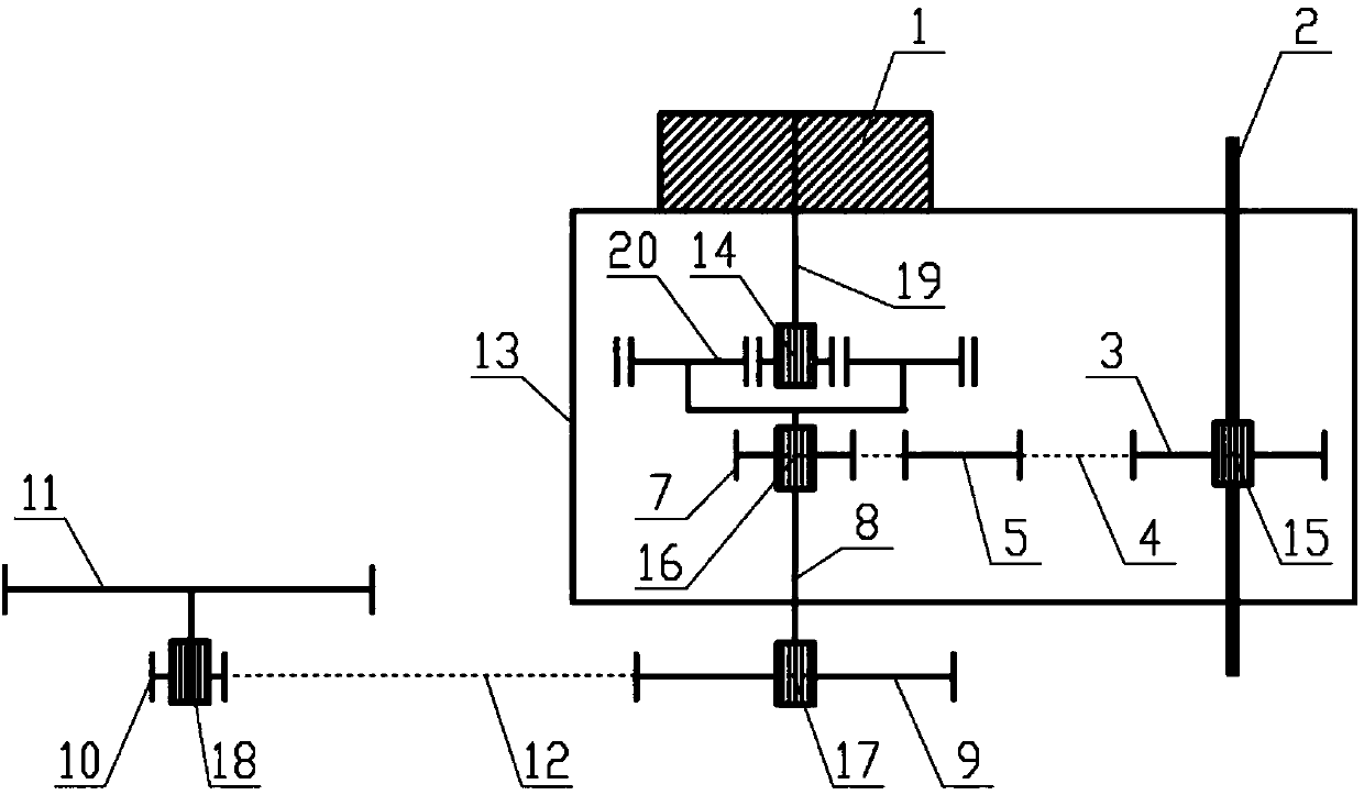
[0084] like figure 2 As shown, the difference between this embodiment and Embodiment 1 is that, in order to increase the assist torque, a planetary gear reducer 20 is also installed in the housing 1, and its sun gear (not shown) is installed on the output shaft 19 of the motor 1 The planetary carrier (not shown) is installed on the drive shaft 8, and the power assist torque output by the motor 1 is amplified by the planetary gear reducer 20 and acts on the drive shaft 8 to achieve greater driving force. Based on this, the torque that the motor 1 actually needs to provide is reduced, and the volume and mass of the motor 1 are also small, which is conducive to the installation of the motor 1 and the weight reduction of the bicycle; in addition, the planetary gear reducer 20 can reduce the length of the housing 13 so that reduce its overall size.

[0085] The fifth one-way device 16 can be arranged between the sun gear and the output shaft 19 of the electric machine 1 .

Embodiment 3

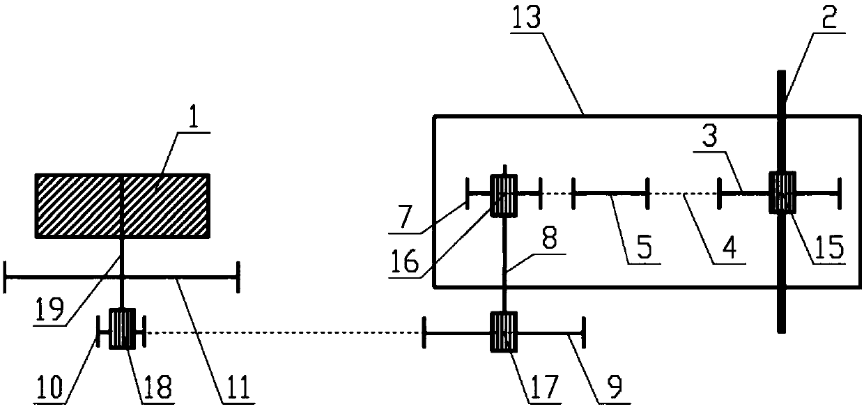
[0087] like image 3 As shown, the difference between this embodiment and Embodiment 1 is that the motor 1 is arranged outside the casing 13 to directly drive the front wheel 21 or the rear wheel 11 of the bicycle. Preferably, the output shaft 19 of the motor 1 is connected to the rear wheel 11 . After the first sensor detects the pedaling force, the motor 1 outputs an assist torque to directly act on the rear wheel 11 . In this embodiment, the motor 1 is a hub motor. Since the motor 1 is not arranged in the casing 13, there is no need to arrange a breathable and waterproof valve on the casing 13.


PUM


Abstract

The invention discloses a power assisting device and a power assisting bicycle. The power assisting device comprises a motor, a crank-set, a drive shaft, a flywheel, a first drive wheel, a second drive wheel and a pedaling force measuring device; a motor controller of the motor controls output of a torque; a transmission connection is established between the crank-set and the first drive wheel through a first chain or a first belt; the transmission connection is established between the second drive wheel and the flywheel through a second chain or a second belt; the first drive wheel and the second drive wheel are installed on the drive shaft; the torque on the first drive wheel can be transmitted to the second drive wheel; the pedaling force measuring device includes a swing arm which swings under the tension of the first chain or the first belt, and a sensor for detecting a rotation angle or a displacement distance of the swing arm; the sensor sends a detected electrical signal to themotor controller; and the motor controller controls the motor to output the corresponding torque. With the power assisting device and the power assisting bicycle disclosed by invention, effective accommodation and sealing for related components can be implemented, thereby improving the reliability of the device.

Description

technical field [0001] The invention belongs to the technical field of electric motor vehicles, and in particular relates to a booster device and a booster bicycle. Background technique [0002] All bicycles using power assist need to be controlled by a motor controller to provide power for the bicycle according to the movement speed or force information of the bicycle. For example, the invention patent with the application number "2017103083387" and the invention title "an integrated power-assisted device and power-assisted bicycle" records a power-assisted scheme, which judges the current driving force that needs to be output by detecting the tension of the chain or belt. In order to achieve the purpose of assistance. Since this power assisting method can accurately reflect the information and state of the current movement of the bicycle, the power assisting effect is better. [0003] However, through long-term use of the product, it has been found that in the technical ...

Claims


Application Information

Patent Timeline
Patent Type & Authority Applications(China)
IPC IPC(8): B62M6/45B62M6/50B62M9/04
CPCB62M6/45B62M6/50B62M9/04
Inventor 王舸殷德军
Owner 南京奥特博机电科技有限公司
Why Eureka
Try Eureka