a vacuum system

A vacuum system and vacuum cover technology, applied in the field of vacuum systems, can solve problems such as actual value deviation, difficulty in replenishing gas volume, and affecting the accuracy and reliability of vacuum pump performance research, so as to improve the accuracy of detection, accurately measure flow, and avoid detection The effect of low precision

Active Publication Date: 2020-04-17
TAIZHOU UNIV
View PDF11 Cites 0 Cited by
  • Summary
  • Abstract
  • Description
  • Claims
  • Application Information

AI Technical Summary

Problems solved by technology

However, the data obtained in this way is only a theoretical value, and there will still be some deviations from the actual value, which will affect the accuracy and reliability of the vacuum pump performance research
Moreover, when the vacuum system is working, the difference in the amount of air supply makes the intake pressure of the screw vacuum pump different, and the measured pressure values ​​will also be different, and it is difficult for the above-mentioned device to measure different degrees of air supply or different intake pressures. Under the conditions, the pressure change law of the vacuum pump cavity

Method used


Image

  • a vacuum system
  • a vacuum system
  • a vacuum system

Examples


Embodiment 1

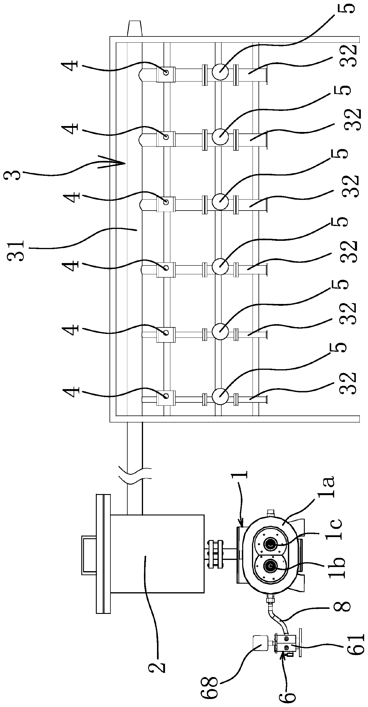
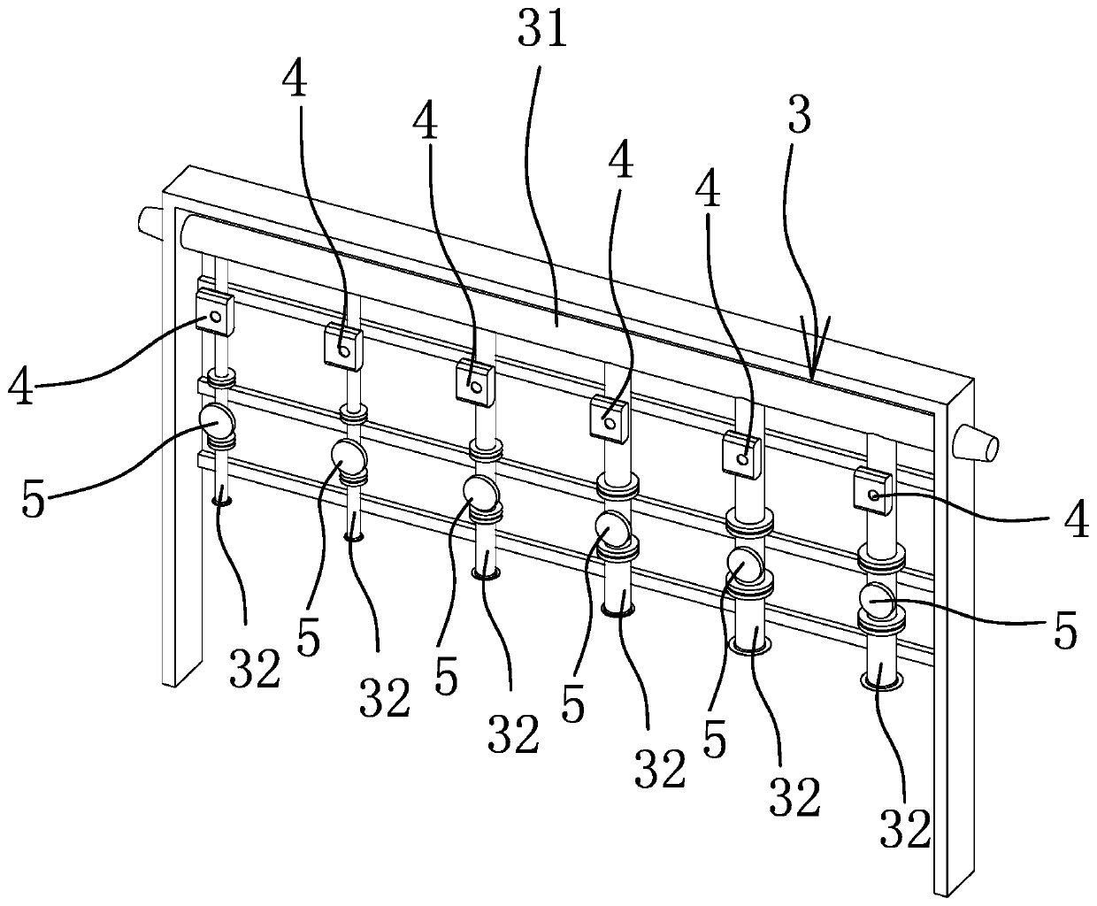
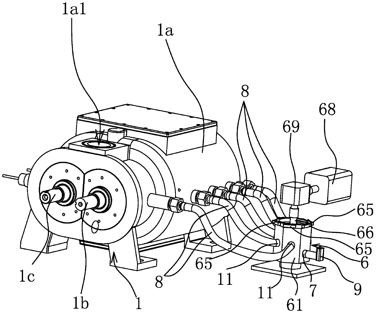
[0033] Such as figure 1 with figure 2 As shown, the vacuum system includes a screw vacuum pump 1 , a vacuum cover 2 connected to the air inlet 1a1 of the screw vacuum pump 1 , and an air supply pipeline 3 for supplying air to the vacuum cover 2 . The air supply pipeline 3 includes a horizontally arranged air supply main pipe 31 and six air supply branch pipes 32 connected with the air supply main pipe 31. The air supply main pipe 31 is connected with the vacuum cover 2, and each air supply branch pipe 32 is provided with a flow rate meter 5 and a flow control valve 4, the vacuum system also includes a controller for receiving the flow signal sent by the flow meter 5 and outputting a control signal to control the opening of the flow control valve 4, the controller is not shown in the figure, each flow Meter 5 and each flow control valve 4 are all connected with the controller. The controller is preferably a single-chip microcomputer, and the flowmeter 5 is preferably a remot...

Embodiment 2

[0045] The structure and principle of this embodiment are basically the same as those of the first embodiment, except that the number of gas supply branch pipes 32 is five, and the diameters of the five air supply branch pipes 32 are all different.

Embodiment 3

[0047] The structure and principle of this embodiment are basically the same as those of the first embodiment, except that the number of gas supply branch pipes 32 is 7, and the diameters of the 7 gas supply branch pipes 32 are all different.


PUM


Abstract

The invention provides a vacuum system, belongs to the technical field of vacuum equipment and aims at solving the problem that the pressure change rule in a screw vacuum pump is difficult to accurately detect under different working conditions in the prior art. The vacuum system comprises an inspection valve, a screw vacuum pump, a vacuum cover and an air supplementing pipeline used for supplementing air to the vacuum cover; the air supplementing pipeline is provided with a flow meter used for measuring an air supplementing flow and a flow control valve used for controlling the size of the air supplementing flow; the side wall of the pump shell is provided with a plurality of exhaust holes communicated with an inner cavity of the pump shell; a plurality of exhaust holes are sequentially arranged at intervals in a length direction of a screw rod; and the inspection valve is provided with an air outlet hole and a plurality of air inlet holes and further comprises an air channel switching structure capable of enabling the air outlet hole to be communicated with any air inlet hole and simultaneously plugging the other air inlet holes if a plurality of air inlet holes are communicatedwith a plurality of exhaust holes in a one-to-one correspondence manner. The vacuum system provided by the invention can more accurately detect the pressure of the screw vacuum pump in the working process.

Description

technical field [0001] The invention belongs to the technical field of vacuum equipment and relates to a vacuum system. Background technique [0002] Vacuum system has been widely used in coating, optics, chemical industry and other fields, the quality of vacuum system directly determines the quality of products. The vacuum system generally includes a vacuum pump, a vacuum cover and an air supply mechanism for supplying air to the vacuum cover. Screw vacuum pump is a commonly used vacuuming equipment. As the power source of the vacuum system, the screw vacuum pump directly affects the stability and reliability of the entire vacuum system. Therefore, the research on the performance of the screw vacuum pump is a particularly important topic. However, at present, there is still a lack of in-depth research on the thermal process experienced by the pumped gas inside the screw vacuum pump, the influence of the thermal process under different inlet pressure (vacuum degree) conditi...

Claims


Application Information

Patent Timeline
Patent Type & Authority Patents(China)
IPC IPC(8): F04B51/00
CPCF04B51/00
Inventor 张莉张永炬
Owner TAIZHOU UNIV
Why Eureka
Try Eureka