
Compressor and air conditioner

A technology for compressors and compression cylinders, which is applied to machines/engines, mechanical equipment, liquid fuel engines, etc., can solve the problems of high noise of compressor exhaust air flow, limitation of muffler performance, and limitation of muffler space structure layout, etc. The effect of noise performance

Pending Publication Date: 2019-04-26
ZHUHAI GREE REFRIGERATION TECH CENT OF ENERGY SAVING & ENVIRONMENTAL PROTECTION
View PDF3 Cites 0 Cited by
  • Summary
  • Abstract
  • Description
  • Claims
  • Application Information

AI Technical Summary

Problems solved by technology

[0003] However, due to space constraints, the spatial structure layout of the muffler above the main bearing or below the sub-bearing is limited, resulting in limited performance of the muffler, and the noise of the exhaust airflow of the compressor is still relatively large

Method used


Image

  • Compressor and air conditioner
  • Compressor and air conditioner

Examples


Embodiment Construction

[0024] Compressor Example:

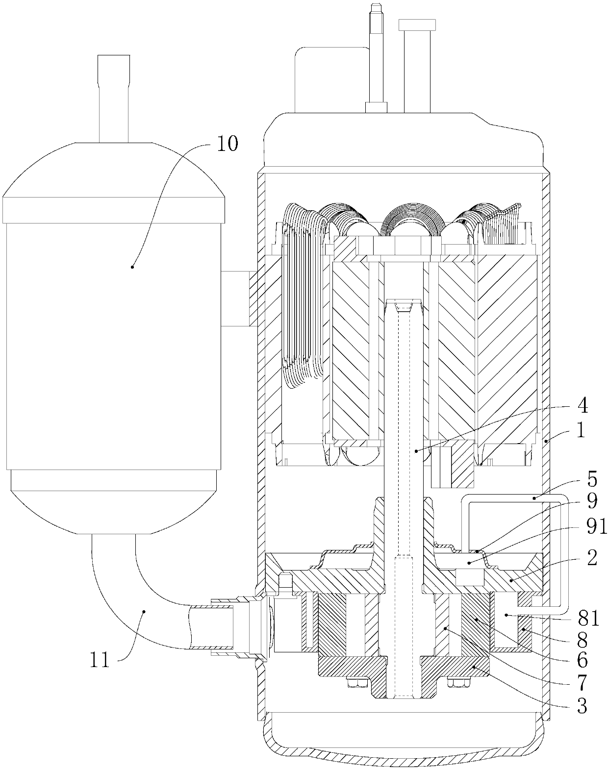
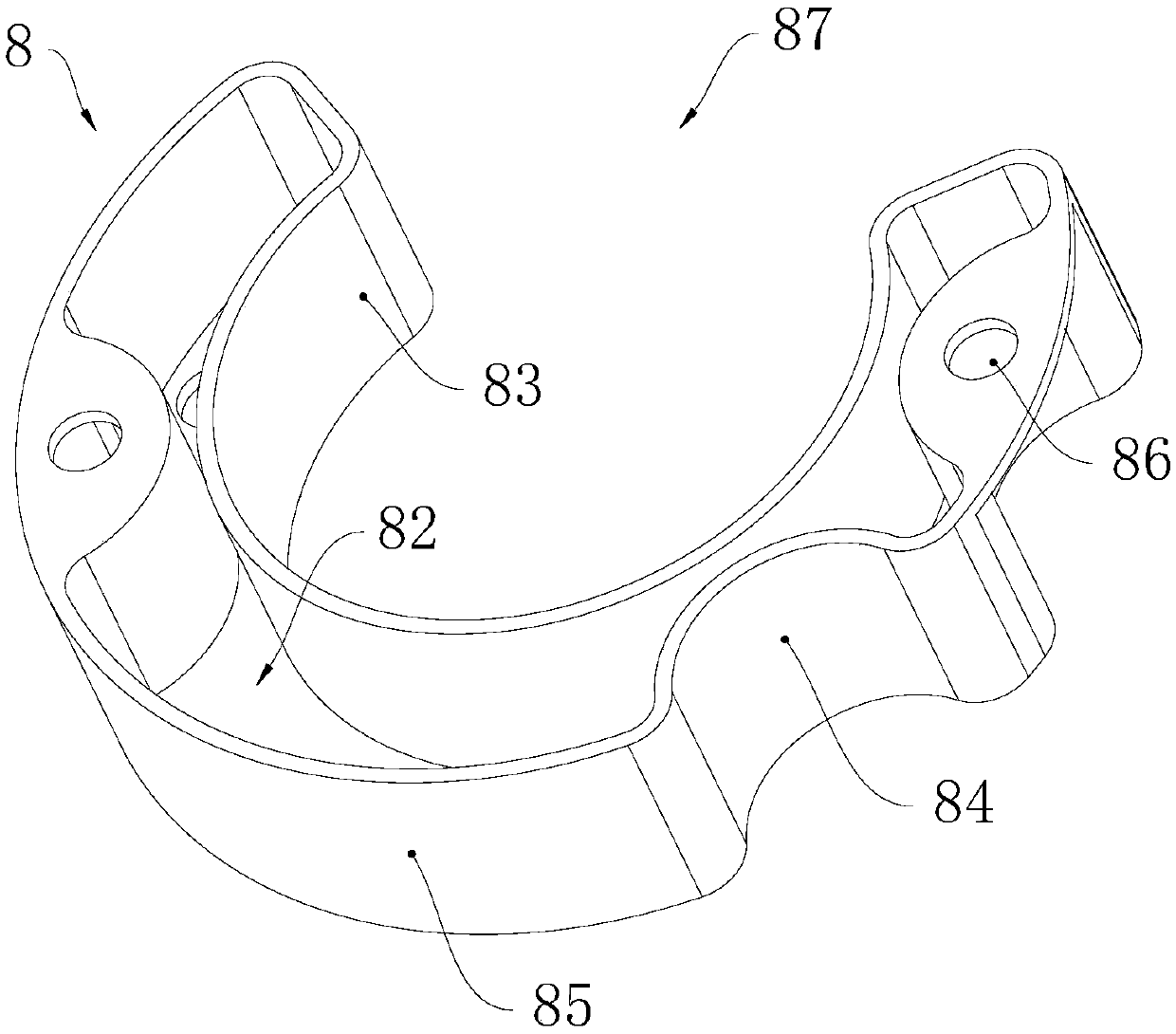
[0025] Please refer to figure 1 and figure 2 , The compressor of this embodiment includes a housing 1, a main bearing 2, an auxiliary bearing 3, a crankshaft 4, a compression cylinder 6, a roller 7, a first muffler 8 and a second muffler 9. The main bearing 2, the auxiliary bearing 3, the crankshaft 4, the compression cylinder 6, the roller 7, the first muffler 8 and the second muffler 9 are all arranged in the housing 1, and the crankshaft 4 is rotatably supported by the main bearing 2 and the auxiliary bearing 3 Above, the roller 7 is sleeved on the connecting rod journal of the crankshaft 4, the roller 7 and the connecting rod journal are located in the cavity of the compression cylinder 6, and the cavity of the compression cylinder 6 has a fluid inlet (not shown in the figure) and a fluid The outlet (not shown in the figure), the fluid inlet communicates with the cavity of the liquid separator 10 through the input pipe 11 .

[0026] In the ...


PUM


Abstract

The invention discloses a compressor and an air conditioner and relates to the technical field of air conditioners. The compressor comprises a first bearing, a second bearing, a compression cylinder,a first silencer and a second silencer; the compression cylinder is located between the first bearing and the second bearing, and is provided with a fluid outlet; the first silencer is located betweenthe first bearing and the second bearing, and is provided with a first silencing cavity; the second silencer is located on the side, deviating from the second bearing, of the first bearing, and is provided with a second silencing cavity; and the fluid outlet, the second silencing cavity and the first silencing cavity communicate with one another in sequence. The air conditioner comprises the compressor. The first silence and the second silence perform two-time denoising on fluid, gas flow noise of the compressor can be lowered easily, and the denoising performance of the compressor is improved. In addition, due to the arrangement of the first silencer, the structural size of the compressor cannot be increased, it is achieved that the denoising performance is improved on the premise that the structural size of the compressor is not increased, and miniaturization design of the compressor is facilitated.

Description

technical field [0001] The invention relates to the technical field of air conditioning, in particular to a compressor and an air conditioner. Background technique [0002] When the compressor is working, due to the characteristics of its working principle, there is inevitably noise influence. The noise of the compressor is generated in many ways, including airflow noise, mechanical noise and electromagnetic noise. Among them, the airflow noise is a main noise source of the compressor, and the noise is mainly caused by the high-pressure fluid pulsation discharged from the compression chamber. In the prior art, in order to reduce the noise of the exhaust air flow of the rotary compressor, a muffler is usually installed above the main bearing or below the auxiliary bearing. The high-pressure fluid discharged from the compression chamber first flows through the muffler for noise reduction, and then from the compressor Fluid outlet discharge. [0003] However, due to space con...

Claims


Application Information

Patent Timeline
Patent Type & Authority Applications(China)
IPC IPC(8): F04C29/06F04C29/00
CPCF04C29/00F04C29/065
Inventor 胡余生魏会军王珺杨欧翔余冰张心爱孙成龙
Owner ZHUHAI GREE REFRIGERATION TECH CENT OF ENERGY SAVING & ENVIRONMENTAL PROTECTION
Learn More