Lifting device of camera and electronic equipment comprising same

A lifting device and electronic equipment technology, applied in the field of machinery, can solve the problems of easy generation of defective products, motor noise and vibration, power consumption, etc., and achieve the effects of fewer defective assemblies, low driving noise, and high retention force.

Inactive Publication Date: 2019-04-26
TIANJIN DELING COMM PARTS CO LTD
View PDF2 Cites 12 Cited by
  • Summary
  • Abstract
  • Description
  • Claims
  • Application Information

AI Technical Summary

Problems solved by technology

[0005] 1. The motor generates noise and vibration during operation;
[0006] 2. The response speed of the motor is slow;
[0008] 4. The standby state will still consume power when there is no action;
[0009] 5. There are many assembly parts, and it is easy to produce defective products
[0010] 6. Large size, takes up a lot of space

Method used


Image

  • Lifting device of camera and electronic equipment comprising same
  • Lifting device of camera and electronic equipment comprising same
  • Lifting device of camera and electronic equipment comprising same

Examples


Embodiment 1

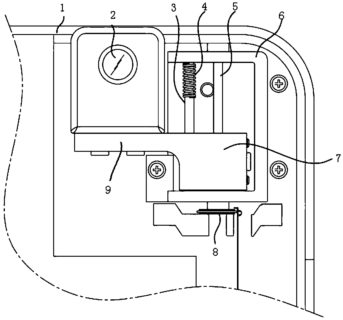
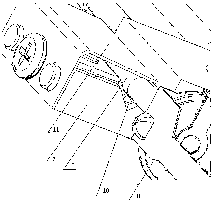
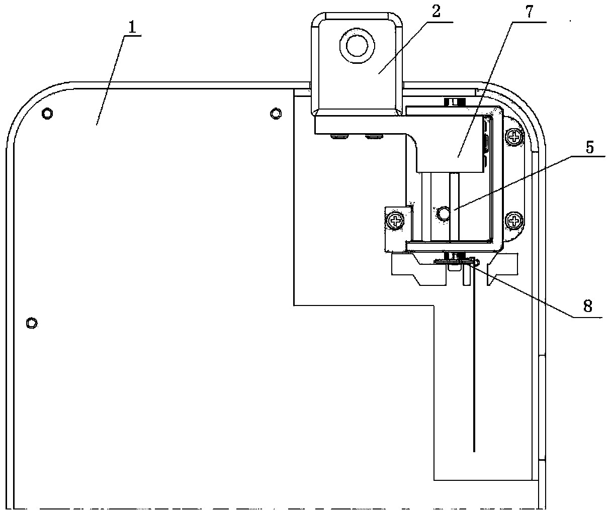
[0034] A lifting device for a camera, comprising a mounting frame 6, an ultrasonic motor assembly 8, a slider 7, a camera bracket 9, an auxiliary rod 3 and a spring 4, the ultrasonic motor assembly is installed on the mounting frame, and the sliding block is installed on the main shaft 5 of the ultrasonic motor. block, a card slot 10 is formed on the side of the slider, the main shaft is embedded in the slot, and a leaf spring 11 is fixed on the slider through bolts, the main shaft is clamped between the slider and the leaf spring, and the function of the leaf spring is to make the slider Tight fit between block and spindle. One end of the slide block is extended outwards to make a camera bracket integrally, and the camera 2 is fixedly mounted on the camera bracket. The slider slides up and down driven by the ultrasonic motor, and the camera slides up and down accordingly.

[0035] An auxiliary rod is fixed on the installation frame parallel to the main shaft at intervals, th...

Embodiment 2

[0039] The difference from Embodiment 1 is that two ultrasonic motors are used to drive the slider, such as Figure 5 As shown, the two ultrasonic motors are parallel and symmetrically installed on the installation frame, and the piezoelectric ceramic ends of the two ultrasonic motors are located on the lower side. Two auxiliary rods are adorned, and a spring is respectively set in the upper and lower sections of the two auxiliary rods.

Embodiment 3

[0041] The difference from Example 2 is that, as Image 6 As shown, one of the piezoelectric ceramic ends of the two ultrasonic motors is on the top and the other is on the bottom.


PUM


Abstract

The invention relates to a lifting device of a camera and electronic equipment comprising the same. The lifting device of the camera comprises a mounting frame, an ultrasonic motor and a slide block.The ultrasonic motor is mounted on the mounting frame and drives the camera to move through the slide block. According to the lifting device of the camera, the ultrasonic motor is adopted, and the reaction speed of the ultrasonic motor is about 10 times faster than that of an electronic motor; the driving noise is quite low; the retentivity is high under power-off conditions; since no electromagnetic coil is used, no free electron wave is produced; and under non-action circumstances, no electric power is consumed.

Description

technical field [0001] The invention belongs to the field of machinery, and relates to smart phones, tablet computers, and laptop computers, in particular to a camera lifting device and electronic equipment including the lifting device. Background technique [0002] CN109257472A discloses a telescopic device and a mobile phone, which has a frame, a screw, a slide block and a driving device for driving the screw to rotate; the screw is arranged on the frame to rotate; the slide block is provided with an internal thread through hole; the screw passes through Through the internal thread through hole and threaded with it; it is characterized in that: the driving device includes a motor and a transmission gear set; the motor is arranged on one side of the screw; one end of the screw is coaxially fixed with a driven gear; the output shaft of the motor The screw rod is driven to rotate through the cooperation of the transmission gear set and the driven gear transmission. The layou...

Claims


Application Information

Patent Timeline
Patent Type & Authority Applications(China)
IPC IPC(8): F16M11/04F16M11/18F16M13/02H04M1/02G06F1/16
CPCF16M11/046F16M11/18F16M13/02F16M2200/04G06F1/1686H04M1/0264
Inventor 金三锺
Owner TIANJIN DELING COMM PARTS CO LTD
Why Eureka
Try Eureka