
A Window Length Determination Method for Moving Principal Component Analysis of Structural Dynamic Response

A principal component analysis and dynamic response technology, applied in instruments, complex mathematical operations, calculations, etc., can solve problems such as inadvisability, surge in calculation amount, delay in health diagnosis time, etc., achieving the effect of small calculation amount and easy operation

Active Publication Date: 2020-08-07
JINAN UNIVERSITY
View PDF6 Cites 0 Cited by
  • Summary
  • Abstract
  • Description
  • Claims
  • Application Information

AI Technical Summary

Problems solved by technology

However, when the window length is too large, it will lead to a surge in the amount of calculations, resulting in delays in health diagnosis time, and cannot reflect the health of the structure in real time
However, in the existing methods, the method of determining the window length is determined by experience, and there is no unified and effective theoretical support and calculation process
In order to achieve the accuracy of calculating the principal components, existing methods select the window large enough, for example, the length of the time window is selected as one year as a cycle to monitor the status of the structure. This selection method is completely inadvisable in the real-time monitoring of the structure. too much time delay

Method used


Image

  • A Window Length Determination Method for Moving Principal Component Analysis of Structural Dynamic Response
  • A Window Length Determination Method for Moving Principal Component Analysis of Structural Dynamic Response
  • A Window Length Determination Method for Moving Principal Component Analysis of Structural Dynamic Response

Examples


Embodiment

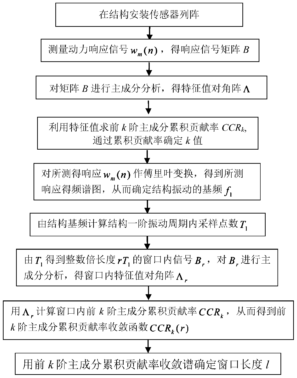
[0048] Such as figure 1 as shown, figure 1 It is a flow chart of the method for determining the window length of the moving principal component analysis based on the structural dynamic response disclosed in the present invention. The structural model used in this embodiment is a steel bridge model, the schematic diagram is as follows figure 2 . The model beam length l is 20m, and the sampling frequency f s 200, the specific implementation process is as follows:

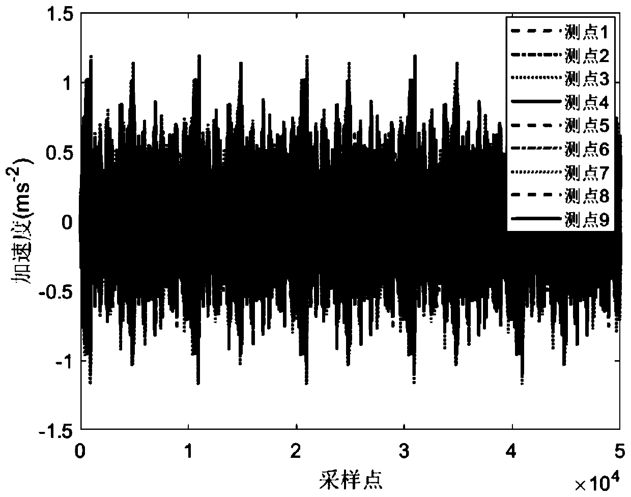
[0049] S1. Measuring the dynamic response of the structure with a sensor array w m (n), to obtain the response signal matrix B, n=1, 2,..., N, m=1, 2,..., M, N is the signal sampling point length, M is the number of measuring points, and N is in the present embodiment 50000, M is 9, the measured dynamic response is as follows image 3 As shown, so the measured response signal matrix B is:

[0050]

[0051] S2, carry out principal component analysis (PCA) to the response signal matrix B in formula (1), get

...


PUM


Abstract

The invention discloses a method for determining the window length of the moving principal component analysis of the dynamic response of the structure. The steps are as follows: install a sensor array on the structure, and measure the dynamic response signal w m (n), get the response signal matrix B; conduct principal component analysis on the matrix B, and get the eigenvalue diagonal matrix Λ; use the eigenvalues ​​to find the cumulative contribution rate CCR of the first k-order principal components k , determine the k value by the cumulative contribution rate; for the measured response w m (n) Perform Fourier transform to obtain the frequency spectrum of the measured response, so as to determine the fundamental frequency f of the structural vibration 1 ; Calculate the number of sampling points T in the first-order vibration period of the structure from the fundamental frequency of the structure 1 ; by T 1 Get the integer multiple length rT 1 Signal B within the window of r ; to B r Perform principal component analysis to obtain the diagonal matrix Λ of eigenvalues ​​in the window r ; use Λ r Calculate the cumulative contribution rate CCR of the first k order principal components in the calculation window k , so that the cumulative contribution rate convergence function CCR of the first k order principal components is obtained k (r); determine the optimal multiple r of the first-order vibration period of the structure using the convergence spectrum of the cumulative contribution rate of the first k-order principal components p ; via r p Compute the optimal window length l.

Description

technical field [0001] The invention relates to the technical field of structural dynamics signal processing, in particular to a method for determining the window length of moving principal component analysis of structural dynamic response. Background technique [0002] Principal component analysis uses a few principal components to represent many variables of the original data, and can retain enough information of the original variables, thereby reducing the difficulty of data analysis. Principal component analysis has two main functions: one is to compress the data, which can reduce the data dimension and reduce the analysis time; the other is to explain the data. The method of principal component analysis can reduce the data containing multiple variables into several principal component data, eliminate redundant information, simplify complex problems, and at the same time make the obtained data more scientific and accurate, so that the model can reflect the real situation...

Claims


Application Information

Patent Timeline
Patent Type & Authority Patents(China)
IPC IPC(8): G06K9/00G06F17/16G06F17/14
CPCG06F17/14G06F17/16G06F2218/08
Inventor 聂振华林逸洲沈兆丰马宏伟
Owner JINAN UNIVERSITY
Learn More