Ice cream self-service vending machine

A self-service vending machine and ice cream technology, which is applied in the field of cold drink equipment, can solve the problems of perishability and other problems, and achieve the effects of reducing operating costs, reducing output power, and saving electric energy

Pending Publication Date: 2019-04-26
南京热冰科技有限公司
0 Cites 7 Cited by

AI-Extracted Technical Summary

Problems solved by technology

[0003] However, the existing ice cream self-service vending machines only maintain a low temperature in the refrigeration module and the ice cream host to ensure that the raw materials that need to be frozen are in a low temperature environment, and other spaces ...

Abstract

The invention relates to an ice cream self-service vending machine. The machine comprises a frame, a front door and a side door which are opened or closed along the frame, a main machine supporting plate which is fixed at the middle part of the frame, wherein an ice cream main machine is fixedly arranged at the upper end of the main machine supporting plate, a refrigeration module is arranged below the main machine supporting plate, a cup dropping mechanism is arranged on one side of the ice cream main machine, a feeder is arranged on the other side of the ice cream main machine, a transmission mechanism is arranged below the cup dropping mechanism, a slurry feeding mechanism is arranged on one side of the feeder, a discharging mechanism fixed on a front door is correspondingly arranged below the slurry feeding mechanism, an operation panel and a face recognition payment system is fixedly installed on the front door, and inner side walls of the front door and the side door are both provided with constant-temperature foaming plates; according to the ice cream self-service vending machine, the refrigerating module is arranged below the inner part of the frame, so that the integral sealing and freezing of the ice cream self-service vending machine are realized by adopting the constant-temperature foaming plate matched with a metal plate at the outer side of the frame, the low-temperature and sterile environment in the cabinet body is ensured, raw materials for making the ice cream, including frozen raw materials, fruit pulp or cream, sugars, oatmeal, etc., are prevented from being deteriorated.

Application Domain

Technology Topic

Image

  • Ice cream self-service vending machine
  • Ice cream self-service vending machine
  • Ice cream self-service vending machine

Examples

  • Experimental program(1)

Example Embodiment

[0042] Hereinafter, the present invention will be described in detail with reference to the drawings and in conjunction with the embodiments. It should be noted that the embodiments of the present invention and the features in the embodiments can be combined with each other if there is no conflict. For the convenience of description, if the words "up", "down", "left", and "right" appear in the following, they only indicate that they are consistent with the upper, lower, left, and right directions of the drawings themselves, and do not limit the structure.
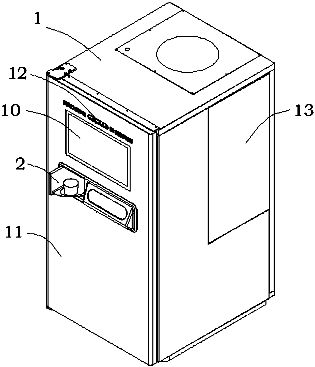
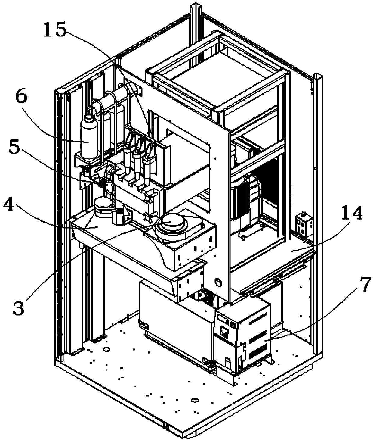
[0043] Such as Figure 1-13 As shown, the structure of the present invention is: an ice cream self-service vending machine, comprising a frame 1, a front door 11 and a side door 13 that open or close along the frame 1, and a host support plate 14 fixed in the middle of the frame 1. An ice cream host 15 is fixedly installed at the upper end of the host support plate 14, and a refrigeration module 7 is arranged below. The ice cream host 15 is provided with a cup drop mechanism 3 on one side and a feeder 5 on the other side. There is a transmission mechanism 4, a slurrying mechanism 6 is provided on one side of the feeder 5, and a discharging mechanism 2 fixed on the front door 11 is correspondingly provided under the slurrying mechanism 6, and the front door 11 is also fixedly installed with an operating mechanism In the panel 10 and the face recognition payment system 12, the inner side walls of the front door 11 and the side door 13 are both provided with thermostatic foaming panels.
[0044] As a preferred technical solution of the present design, the discharging mechanism 2 includes a main frame plate 21 fixed on the front door 11, and the central part of the main frame plate 21 protrudes outward to form a visible window 22. The visible window A transparent glass 23 is embedded in the middle of 22, a power device 24 is provided on the rear side of the main frame plate 21, and the power device 24 is rotatably connected to a cup taking door 25, and a cup 26 is placed on the cup taking door 25.
[0045] As a preferred technical solution of this design, the power device 24 includes a discharging motor 241 fixed on the main frame plate 21, and the discharging motor 241 is motively connected to a rotating shaft that cooperates with the cup taking door 25. One side of the motor 241 is provided with an automatic lock 242 that cooperates with the cup taking door 25, and both sides of the cup taking door 25 are respectively provided with a door opening sensor 244 and a door closing sensor 246 fixed on the main frame plate 21. The cup taking door An induction sensor 245 and a baffle 243 are installed on the 25.
[0046] As a preferred technical solution of the present design, the cup taking door 25 includes an outer door 251, a cup bearing plate 252, and an inner door 254 that are perpendicular and fixedly connected in pairs. One end of the outer door 251 is provided with a rotating shaft. The cup supporting plate 252 is provided with a cup limiting groove 253 for limiting the cup 26, and the inner door 254 is provided with a mounting hole 256 for installing the induction sensor 245.
[0047] As a preferred technical solution of this design, the transmission mechanism 4 includes a beam support 41, a transmission motor 42 is fixedly installed on the beam support 41, and a power shaft of the transmission motor 42 is connected to a driving pulley 43. The pulley 43 is connected to the driven pulley 45 through a timing belt 44, the middle of the timing belt 44 is connected to the moving device 46, the upper end of the moving device 46 is installed with a manipulator 47, the side of the beam bracket 41 is located under the manipulator 47 and fixedly connected For the material trough 48, the two ends of the moving device 46 are slidably connected to the silent line rail 49 fixed on the beam support 41.
[0048] As a preferred technical solution of this design, the moving device 46 includes a mounting plate 464 connected to the silent line rail 49, a lifting motor 461 is installed at the lower end of the mounting plate 464, and the lifting motor 461 is connected to a lifting screw 462, The lifting screw 462 is connected to the lifting adapter plate 463 through a sliding table, and one end of the lifting adapter plate 463 is connected to the manipulator 47.
[0049] As a preferred technical solution of this design, the manipulator 47 includes a claw clip motor 471 fixed on the lifting adapter plate 463, the claw clip motor 471 is power connected to the driving shaft 472, the lifting adapter plate 463 is also fixed There is a driven shaft 473 corresponding to the driving shaft 472. The outer sides of the driving shaft 472 and the driven shaft 473 are respectively sleeved with claw clamps 474 engaged with each other. The claw clamps 474 include a claw clamp body 475, and the claw clamp body 475 One end is an arc-shaped arm 478 matching the material cup, the other end is provided with a transmission tooth 477, and the end close to the transmission tooth 477 is provided with a shaft hole 476.
[0050] As a preferred technical solution of the present design, the feeder 5 includes a feeding box body 51 fixed on the side of the ice cream host 15, the feeding box body 51 is a box-like structure with an open upper end, and its upper end is matched with a feeding box cover 52 , The front side is connected with the discharge port 53 through, and a feeding screw 54 is provided at the bottom. The feeding screw 54 is connected to the gear assembly 55 for rotation, and the gear assembly 55 is connected to the feeding motor 56.
[0051] As a preferred technical solution of this design, the slurrying mechanism 6 includes a slurrying frame plate 61 fixed on the inner side wall of the frame 1, and a peristaltic pump 65 is fixedly installed on the slurrying frame plate 61. The peristaltic pump A slurry bottle 62 is placed above 65, a slurry pipe 63 is inserted into the slurry bottle 62, the middle of the slurry pipe 63 is laid on the slurry pipe bracket 64, and the other end is connected to the peristaltic pump 65.
[0052] As a preferred technical solution of this design, the refrigeration module 7 includes a compressor assembly 71, an electrical installation box 72, and an evaporator assembly 73 integratedly installed in the rack 1, and the electrical installation box 72 includes an electrical control box The supporting plate 721 and the electric control box housing 722 also include a socket 723 fixed on the outer side wall of the electric control box housing 722 and a control panel 724. The electric control box housing 722 is provided with electrical components 725 and a switching power supply 726.
[0053] Specific use:
[0054] S1. The purchaser selects the ice cream of his favorite flavor through the operation panel 10, confirms whether additional material selection is required and confirms to place an order, and completes the payment of the order through the payment interface of the operation panel 10 or the face recognition payment system 12;
[0055] S2. The operation panel 10 sends the order information to the electrical installation box 72. The electrical installation box 72 first sends instructions to the cup drop mechanism 3 according to the order information to push out the lowest cup 26 and drop it into the claw clamp 474 of the manipulator 47. The clamping motor 471 drives the claw clamp 474 through the transmission teeth 477 to complete the clamping of the material cup, and the lifting motor 461 rotates to drive the material cup 26 down;
[0056] S3. The transmission motor 42 rotates, and under the cooperation of the driving pulley 43, the timing belt 44, the driven pulley 45 and the silent linear rail 49, the material cup 26 is transported to the ice cream host 15, the feeder 5 and the pulping mechanism 6, respectively. To complete the production of ice cream, the overflowing material during the feeding and transportation process falls into the trough 48 and is cleaned regularly. At the same time, consumers can not only observe the entire ice cream production process in real time through the visual window 22, but also understand the vending machine Internal hygiene;
[0057] S4. After the ice cream is made, the manipulator 47 transports the finished product to the top of the cup taking door 25, and the claw clamp motor 471 rotates to drive the claw clamp 474 to loosen the cup 26 and lower it into the cup limit groove 253 of the cup support plate 252 After the inductive sensor 245 senses it, it transmits the message to the discharge motor 241 and the automatic lock 242. The automatic lock 242 retracts. The discharge motor 241 drives the outer door 251 to rotate 90 degrees through the rotating shaft. The outer door 251 is outside while the inner door 254 is sealed. Window until the baffle 243 touches the door opening sensor 244, effectively preventing the hot air from entering the cabinet to reduce the temperature;
[0058] S5. After the consumer takes out the ice cream product, the inductive sensor 245 transmits the message to the discharging motor 241 and the automatic lock 242. The discharging motor 241 drives the outer door 251 to rotate 90 degrees in the opposite direction through the rotating shaft until the baffle 243 touches When the door closing sensor 246 is reached, the automatic lock 242 is extended to complete the closing.
[0059] At this point, the ice cream production process has been completed, and the cycle as above should be repeated when it is needed again.
[0060] The above are only the embodiments of the present invention, which do not limit the scope of the present invention. Any equivalent structure or equivalent process transformation made by using the description and drawings of the present invention, or directly or indirectly applied to other related technologies In the same way, all fields are included in the scope of patent protection of the present invention.

PUM

no PUM

Description & Claims & Application Information

We can also present the details of the Description, Claims and Application information to help users get a comprehensive understanding of the technical details of the patent, such as background art, summary of invention, brief description of drawings, description of embodiments, and other original content. On the other hand, users can also determine the specific scope of protection of the technology through the list of claims; as well as understand the changes in the life cycle of the technology with the presentation of the patent timeline. Login to view more.

Similar technology patents

Method and system for automatically conveying packages, robot and storage device

ActiveCN108401423AReduce human-involved componentsReduce labor costsSortingEngineeringRobot
Owner:SHENZHEN DORABOT ROBOTICS CO LTD

Classification and recommendation of technical efficacy words

  • Reduce labor costs
  • Reduce operating costs

Thin-skin ultralight recreational vehicle body system

InactiveUS7000978B1Elimination of bonding processReduce labor costsVehicle seatsSuperstructure subunitsExtremely lightVehicle frame
Owner:MESSANO FR
Why Eureka
Try Eureka